Do you have a question about the Fujitsu ABYG30LRTE and is the answer not in the manual?
| Brand | Fujitsu |
|---|---|
| Model | ABYG30LRTE |
| Category | Air Conditioner |
| Language | English |
Overview of available indoor unit models and their configurations.
Detailed technical specifications for various indoor unit types, including airflow, power, and dimensions.
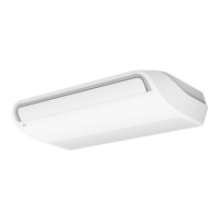
Technical specifications for the compact cassette indoor unit models.
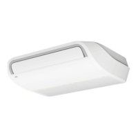
Technical specifications for the cassette indoor unit models.
Technical specifications for the slim duct indoor unit models.
Technical specifications for the duct indoor unit models.
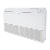
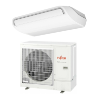
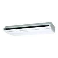
Technical specifications for the floor/ceiling indoor unit models.
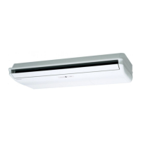
Technical specifications for the ceiling indoor unit models.
Dimensional drawings and measurements for indoor unit installation.
Installation dimensions for compact cassette indoor units.
Installation dimensions for cassette indoor units.
Installation dimensions for slim duct indoor units.
Installation dimensions for duct indoor units.
Installation dimensions for floor/ceiling indoor units.
Installation dimensions for ceiling indoor units.
Electrical connection diagrams for indoor units.
Wiring diagrams specific to compact cassette indoor units.
Wiring diagrams specific to cassette indoor units.
Wiring diagrams specific to slim duct indoor units.
Wiring diagrams specific to duct indoor units.
Wiring diagrams specific to floor/ceiling indoor units.
Wiring diagrams specific to ceiling indoor units.
Airflow patterns and temperature distribution charts for indoor units.
Airflow and temperature distribution for compact cassette units.
Airflow and temperature distribution for cassette units.
Airflow and temperature distribution for slim duct units.
Airflow and temperature distribution for floor/ceiling units.
Airflow and temperature distribution for ceiling units.
Fan performance curves showing airflow vs. static pressure.
Fan performance data for slim duct units.
Fan performance data for duct units.
Airflow rates for various fan speeds and modes for indoor units.
Airflow data for compact cassette indoor units.
Airflow data for cassette indoor units.
Airflow data for slim duct indoor units.
Airflow data for duct indoor units.
Airflow data for floor/ceiling indoor units.
Airflow data for ceiling indoor units.
Sound pressure level curves for various indoor unit types.
Noise level curves for compact cassette indoor units.
Noise level curves for cassette indoor units.
Noise level curves for slim duct indoor units.
Noise level curves for duct indoor units.
Noise level curves for floor/ceiling indoor units.
Noise level curves for ceiling indoor units.
Diagrams showing microphone placement for sound level measurement.
Electrical requirements, including power supply and circuit breaker ratings.
Information on protective functions and safety devices for indoor units.
List of optional accessories for indoor units.
Accessories for compact cassette indoor units.
Accessories for cassette indoor units.
Accessories for slim duct indoor units.
Accessories for duct indoor units.
Accessories for floor/ceiling indoor units.
Accessories for ceiling indoor units.
Detailed technical specifications for outdoor units.
Dimensional drawings for outdoor unit installation.
Installation dimensions for specific outdoor unit models.
Requirements for safe and proper outdoor unit installation space.
Installation space requirements for specific outdoor unit models.
Diagrams illustrating the refrigerant flow within the system.
Refrigerant circuit diagrams for specific outdoor unit models.
Electrical connection diagrams for outdoor units.
Wiring diagrams for specific outdoor unit models.
Cooling and heating capacity tables for outdoor units.
Cooling capacity data for AOYG72LRLA model.
Cooling capacity data for AOYG90LRLA model.
Tables for calculating capacity adjustments based on piping length and height.
Capacity compensation rates for AOYG72LRLA model.
Capacity compensation rates for AOYG90LRLA model.
Airflow specifications for outdoor units.
Airflow data for AOYG72LRLA model.
Airflow data for AOYG90LRLA model.
Noise level curves for outdoor units.
Sound pressure level charts for outdoor units.
Diagrams showing microphone placement for sound level measurement.
Electrical specifications for outdoor units.
Safety devices and protection mechanisms for outdoor units.
List of optional accessories for outdoor units.
General guidelines and precautions for installing the system.
Precautions specifically for installing indoor units.
Precautions specifically for installing outdoor units.
Guidelines for designing the refrigerant piping system.
Key considerations for using R410A refrigerant and piping.
Maximum allowable piping lengths and height differences.
Recommended pipe sizes based on capacity and type.
Guidelines for selecting appropriate heat insulation for refrigerant pipes.
Procedures for calculating and adding refrigerant.
Procedures and precautions for installing refrigerant piping.
Important cautions and material requirements for piping installation.
Steps for connecting pipes to the outdoor unit.
Methods and precautions for connecting refrigerant pipes.
Selection and installation of branch pipes for multi-systems.
Guidelines for designing the electrical wiring system.
Safety precautions and regulations for electrical wiring.
Specifications and diagrams for power supply and control cables.
Diagrams and explanations of various remote controller control configurations.
Procedures for setting up system configurations for indoor units.
Settings for indoor unit addressing and operation modes.
How to use external signals for unit control and status monitoring.
External input/output functions for indoor units.
External input/output functions for outdoor units.
Information on different types of remote controllers and their usage.
Overview and specifications of wireless remote controllers.
Specifications for the optional IR receiver kit.
Specifications for the optional IR receiver kit.
Overview and specifications of the wired remote controller.
Overview and specifications of the optional wired remote controller.
Overview and specifications of the optional simple remote controller.
How to configure various unit functions via switches or remote controllers.
Setting indoor unit functions using DIP switches and jumper wires.
Setting indoor unit functions using a wireless remote controller.
Setting indoor unit functions using a wired remote controller.
Setting indoor unit functions using a simple remote controller.
Local setting switches and functions on the outdoor unit.
Detailed explanation of available function settings for indoor units.
DIP switch settings for the UTY-RNNYM wired remote controller.
DIP switch settings for the UTY-RVNYM wired remote controller.
DIP switch settings for the UTY-RSNYM simple remote controller.
Procedures for pre-test checks, test operation, and checklists.
Steps for performing the initial test operation of the system.
Explanation of error codes and troubleshooting steps.
Procedure for safely removing refrigerant from the system.
Installation instructions for optional accessories.
Installation of a drain pump for duct type indoor units.
Installation of a drain pump for ceiling type indoor units.
Installation of a fresh air intake kit for cassette units.
Installation of a fresh air intake kit for compact cassette units.
Installation of an auto louver grille kit.
Specifications and models of branch pipes for multi-systems.
Specifications for UTP-SX272A branch pipes.
Specifications for UTP-SX372A branch pipes.
Specifications for UTP-SX236A branch pipes.
Specifications for UTP-SX254A branch pipes.
Lineup and parts for various remote controllers.
List of available remote controller models and their compatibility.
Images and names of controller parts.
Lineup and parts for cassette grilles.
Available cassette grille models.
Images of cassette grille parts.
Other optional parts and their specifications.
List of other optional parts.
Images of other optional parts.