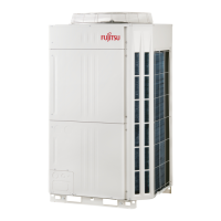
Do you have a question about the Fujitsu Airstage AJYA72LALH and is the answer not in the manual?
| Brand | Fujitsu |
|---|---|
| Model | Airstage AJYA72LALH |
| Category | Air Conditioner |
| Language | English |
Crucial safety warnings and cautions for installation and usage.
Essential guidelines for handling and using R410A refrigerant.
Lists specialized tools required for R410A refrigerant systems.
Lists included accessories and details allowable indoor/outdoor unit combinations.
Lists optional parts specific to R410A refrigerant, including branch kits, separation tubes, and headers.
Guidelines for choosing a suitable and safe location for unit installation.
Instructions for proper drainage system setup.
Specifies required clearances and dimensions for installation.
Installation clearances near walls of specific heights.
Installation clearances near walls without height restrictions.
Installation requirements when obstacles are present above the unit.
Methods and precautions for safely transporting the outdoor unit.
Explains how to configure multiple outdoor units for a system.
System configuration for a single outdoor unit.
System configuration for two connected outdoor units.
System configuration for three connected outdoor units.
Guidelines for selecting appropriate refrigerant pipe sizes.
Measures to protect refrigerant pipes from moisture and dust.
Procedures and precautions for brazing refrigerant pipes.
Steps for connecting refrigerant pipes to indoor units.
General methods for routing and connecting refrigerant pipes.
How to open and prepare knockout holes for pipe entry.
Procedure for safely removing pinch pipes.
Detailed steps for connecting refrigerant pipes.
Guidelines for connecting multiple outdoor units.
Further guidelines and examples for connecting multiple outdoor units.
Essential safety warnings for electrical wiring.
General wiring procedures for outdoor and indoor units.
Precautions for preparing knockout holes for wiring.
Guidance on choosing appropriate power cables and breakers.
Specifications and precautions for transmission wiring.
Details on transmission cable types and specifications.
Rules and limitations for transmission line wiring.
Step-by-step instructions for electrical wiring connections.
How to enable/disable automatic address setting for units.
Information on external input/output terminals and their functions.
Identifies terminal positions on the outdoor unit PC board.
Details on external input terminals and their wiring.
Information on external output terminals for status indication.
Details on the base heater terminal and its function.
Location of switches for field settings on the PC board.
Configuration of DIP switches for various settings.
A list of DIP switch settings and their functions.
How to configure local settings like unit address.
Procedure for setting terminal resistors for network communication.
How to set the rotary switch for refrigerant circuit address.
How to use push buttons for various function settings.
How to set addresses for signal amplifiers.
How to set addresses for signal amplifiers.
Steps to enable automatic address setting for signal amplifiers.
Manual and automatic methods for setting indoor unit addresses.
Manual and automatic methods for setting indoor unit addresses.
Steps to enable automatic address setting for indoor units.
How to measure transmission cable resistance.
Procedure for performing a sealing test on refrigerant pipes.
Steps for performing a vacuum process on the refrigeration system.
Instructions for adding refrigerant to the system.
Step-by-step guide for refrigerant charging.
How to calculate and check total refrigerant amounts.
Guide on installing insulation material on refrigerant pipes.
Checklist of items to verify before starting a test run.
Procedures for conducting test runs on the unit.
Final checklist for verifying correct operation.
Explains LED indicators for normal operation status.
Lists and explains error codes indicated by LEDs.
Details the information found on the unit's label.




 Loading...