Do you have a question about the Fujitsu Airstage ARUM24TLAV2 and is the answer not in the manual?
Crucial advice to read the installation manual thoroughly before proceeding.
Essential safety guidelines for electrical wiring and unit handling during transport.
Specific warnings and safety measures for handling R410A refrigerant.
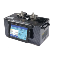
Details on dedicated tools necessary for R410A refrigerant system installation.
Lists the essential parts provided with the unit for installation.
Overview of optional components for enhancing system functionality or compatibility.
Guidance on choosing a suitable and safe location for the indoor unit.
Specifies the necessary clearances and dimensions for proper unit installation.
Guidelines for choosing appropriate copper pipes for R410A systems.
Details on pipe requirements, heat insulation, and pressure considerations.
Instructions for flaring pipes and bending them without damage or leaks.
Guidance on applying heat insulation to refrigerant pipes and couplers.
Details on pipe material, insulation, gradient, supports, and connection.
Specifications for power supply, voltage, and circuit breakers.
Specifications for connecting transmission and remote controller cables.
Detailed instructions for connecting power supply and communication cables.
Explains connections for power supply, transmission, and remote controller cables.
Step-by-step guide for connecting power supply and communication cables.
Instructions for wiring various optional components like remote sensors and drain pumps.
Details on connecting external devices for input/output control.
Instructions for connecting and setting up the optional remote sensor.
Steps for installing and connecting the IR receiver unit.
Guidance on installing and connecting the optional drain pump unit.
Methods for setting indoor unit and refrigerant circuit addresses.
Procedure for setting custom codes to prevent indoor unit mix-ups.
Guidelines for setting static pressure modes for optimal airflow.
Details on various function settings for filter indicators, auto restart, and controls.
Procedure for performing a test run using the outdoor unit's control board.
Instructions for conducting a test run using the wireless remote controller.
This document serves as an installation manual for the AIRSTAGE™ indoor unit (Duct type) of a VRF system, intended exclusively for authorized service personnel. It provides comprehensive instructions for safe and efficient installation, operation, and maintenance. The manual emphasizes the importance of adhering to safety precautions, proper installation techniques, and the use of specified tools and materials to ensure the system's longevity and prevent accidents.
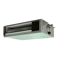
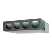
The AIRSTAGE™ indoor unit (Duct type) is a component of a VRF (Variable Refrigerant Flow) air conditioning system, designed to provide heating and cooling to indoor spaces. As a duct-type unit, it is typically concealed within a ceiling or wall, distributing conditioned air through a network of ducts to various rooms or zones. This design allows for discreet installation, maintaining the aesthetic integrity of the space while delivering effective climate control.
The unit supports various operational modes, including "Operation/Stop," "Emergency stop," and "Forced stop," which can be controlled via the indoor unit PCB or a remote controller. These modes allow for flexible management of the air conditioning system, adapting to different user needs or emergency situations. For instance, the "Emergency stop" mode can halt all indoor units in the same refrigerant system, providing a critical safety feature. The "Forced stop" mode restricts operation by a remote controller, offering another layer of control.
The system incorporates a "Fresh air intake" feature, allowing for the introduction of fresh outdoor air into the conditioned space. This enhances indoor air quality by diluting pollutants and maintaining a comfortable environment. The manual details the process of cutting a slit-shaped cabinet and installing a round flange for duct connection, ensuring proper sealing to prevent air leakage.
The unit's fan settings can be configured for external heaters, allowing for integrated control of supplementary heating sources. This feature enables the system to optimize heating performance based on external conditions and user preferences. Additionally, the system supports various static pressure modes, which can be adjusted to match the specific requirements of the ductwork and ensure efficient air distribution.
External input and output functions are available, allowing the indoor unit to interface with other devices such as ventilators, economizers, or humidifiers. These functions can be configured for "Start/Stop," "Emergency stop," or "Forced thermostat off" modes, providing versatile integration capabilities. The system also supports remote sensor connections for accurate room temperature measurement and correction, ensuring precise climate control.
The AIRSTAGE™ indoor unit is designed for user convenience and operational flexibility. The system's address and refrigerant circuit address can be set manually using rotary switches on the unit or through a wireless remote controller, simplifying the configuration process for multi-unit installations. Custom code settings prevent mix-ups in installations with multiple indoor units, ensuring that each unit responds to its designated controls.
The unit features a power indicator lamp (green) that provides visual feedback on its operational status. A steady green light indicates normal operation, while fast flashing or blinking patterns signal communication board faults or power supply issues from an external unit. This visual cue helps in quick diagnosis of potential problems.
The remote controller offers a user-friendly interface for managing the system. It allows users to perform test runs, adjust settings, and monitor the unit's status. In case of errors, the remote controller displays error codes, which correspond to specific issues detailed in the manual, facilitating troubleshooting.
The system includes a "Filter indicator interval" function, which can be adjusted to notify users when the air filter needs cleaning. This feature promotes regular maintenance, ensuring optimal performance and air quality. The "Cool air temperature trigger" and "Heat air temperature trigger" functions allow users to fine-tune the system's response to temperature changes, enhancing comfort.
An "Auto restart" function enables the system to automatically resume operation after a power outage, ensuring continuous climate control without manual intervention. The "Cool Air Prevention" feature restrains cold airflow during heating startup, preventing uncomfortable drafts.
The unit's design allows for flexible air intake configurations, including bottom air intake, which can be changed by replacing the intake grille and flange. This adaptability caters to different installation requirements and aesthetic preferences.
The manual provides detailed instructions for maintenance, emphasizing the importance of regular checks and proper procedures. The "Check List" section at the end of the manual serves as a comprehensive guide for installers to verify that all installation steps have been completed correctly and that the unit is operating safely and efficiently. This includes checks for gas leaks, heat insulation, drainage, electrical connections, and proper earthing.
The system's design facilitates servicing, with specific recommendations for maintaining adequate service access around the unit. This ensures that authorized service personnel can easily inspect and repair electrical parts, wiring, and other components. The manual advises against placing wiring or illumination in the service space to avoid impeding service.
The "Filter indicator interval" and "Filter indicator action" functions are crucial for proactive maintenance. These features remind users to clean or replace the air filter, which is essential for maintaining air quality and preventing the heat exchanger from becoming clogged, thereby preserving the unit's performance.
The manual highlights the importance of using specified tools and materials for R410A refrigerant systems, such as dedicated flare tools and piping materials, to prevent rupture or injury due to the higher pressure of R410A. It also provides instructions for proper pipe connection, including tightening torques for flare nuts, to ensure leak-free connections and prevent hazardous gas leaks.
Instructions for installing heat insulation around pipes and drain hoses are provided to prevent "sweating" and water damage. The manual also details the proper installation of drain pipes, including maintaining a downward gradient and providing supporters for long pipes, to ensure smooth drainage and prevent freezing.
For electrical wiring, the manual specifies the types and sizes of cables to be used, as well as proper connection methods, to prevent electric shock, fire, and malfunction. It emphasizes the importance of earthing the unit and connecting cables securely to the terminal board. The power indicator lamp's flashing patterns and error codes displayed on the remote controller are valuable diagnostic tools for identifying and resolving issues, streamlining the maintenance process.
| Capacity (Cooling, Btu/h) | 24000 |
|---|---|
| Capacity (Heating, Btu/h) | 27000 |
| HSPF | 9.0 |
| Refrigerant | R410A |
| Phase | 1 |
| Maximum Number of Connectable Indoor Units | 4 |
| Voltage (V) | 208-230 |