En-13
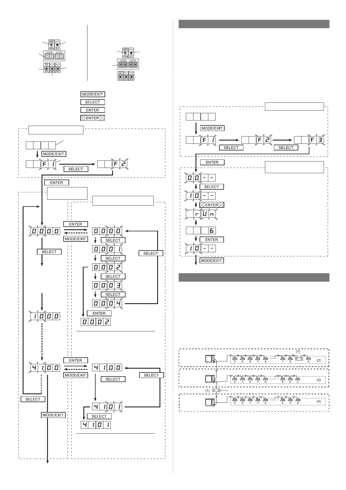
(1) Turn on the power of the outdoor unit and enter standby mode.
• When system is normal
POWER/MODE lamp lights up. (ER-
ROR lamp is off.)
• When system is abnormal
Check the settings as there is an error in the
settings for outdoor unit address
(DIP switch SET 3-1, 2) or number of con-
nected slave units (DIP switch SET 3-3, 4).
POWER/MODE
lamp: ON
ERROR
lamp: OFF
SELECT button
ENTER
button
MODE/EXIT
button
7 segment
display:
turn off
POWER/MODE
lamp: ON
7 segment
display: “-”
display
ERROR lamp:
Blinking
(2) Setting method
Use the “MODE/EXIT”, “SELECT”,
and “ENTER” buttons to configure
settings according to the proce-
dures below.
(If no setting is made, the factory
default setting will be displayed.)
: Press the “MODE/EXIT” button
: Press the “SELECT” button
: Press the “ENTER” button.
: Press the “ENTER” button for
more than 3 seconds.
1: Function setting
7 segment LED display (LED 105, LED 104)
(Blinking)
First 2 digits
Last 2 digits
(When [F3] to [F9] are displayed, continue to press
the “SELECT” button until [F2] is displayed.)
2: Setting the first
2 digits
3: Setting the last 2 digits
Continue to press the “SELECT” button until the
desired number appears at the last 2 digits.
Every press of the
“SELECT” button will
change the setting
number for the first 2
digits.
(Continue to press the “SE-
LECT” button until the desired
number appears at the last 2
digits.)
Setting is complete when the lamp lights up
Press “ENTER” button to return to “2. Setting the
first 2 digits” (If there is no operation for 5 seconds
after the setting, the display will return to “2: Setting
the first 2 digits”.)
Setting is complete when the lamp lights up
Press “ENTER” button to return to “2. Setting the
first 2 digits” (If there is no operation for 5 seconds
after the setting, the display will return to “2: Setting
the first 2 digits”.)
EXIT: Press the “MODE/EXIT” button to cancel the setting mode.
7.5. Address setting for Signal amplifi ers
7.5.1. Address setting for Signal amplifi ers
When using Signal amplifiers, the address for Signal amplifiers must be set.
The address for Signal amplifiers can be set automatically from 1 outdoor unit (master
unit) on the network.
Refer to “Fig. Wiring example for automatic address setting” (7.6.1 chapter) for the wiring
example.
(For manual setting of address, refer to the Signal amplifier installation manual.)
7.5.2. Automatic address setting for Signal amplifi ers
When setting the address of the Signal amplifier, please use the factory setting. (See the
installation manual of the Signal amplifier)
• When the system is normal, nothing will be displayed on the 7 segment display.
• When ERROR is displayed, inspect the units.
Use the “MODE/EXIT”, “SELECT”, and “ENTER” buttons on the outdoor unit PC board to
configure settings according to the procedures below.
1: Function setting
First 2 digits Last 2 digits
(the display when the main power is turned on)
Set to Function mode [F3].
(When [F4] to [F9] are displayed, continue to press
the “SELECT” button until [F3] is displayed.)
Automatic address setting for
Signal amplifiers
Press the “SELECT” button until “10” is displayed.
Press the “ENTER” button for more than 3 seconds.
Setting is complete when the number of units is displayed
End
7.6. Indoor unit address setting
7.6.1. Indoor unit address setting
Address must be set for the indoor unit.
Manual setting
→
• When setting with the switch inside the indoor unit, refer to
the indoor unit operating manual.
• When setting with a remote control, refer to the remote control
operating manual.
Automatic setting
→
• Check that the wiring is as shown in the figure below. Operate
using the outdoor master unit of each refrigerant system.
Fig. Wiring example for automatic address setting
(1): Signal amplifier wiring example
(2)(3)(4): Indoor unit wiring example
(Connect the indoor and outdoor units of the same refrigerant system as shown below.)
Refrigerant system 1
Refrigerant system 2
Refrigerant system 3
Master unit
Master unit
Master unit
Signal amplifier
Signal amplifier
9380545378-03_IM.indb 139380545378-03_IM.indb 13 2022/10/26 10:24:582022/10/26 10:24:58
 Loading...