03-23
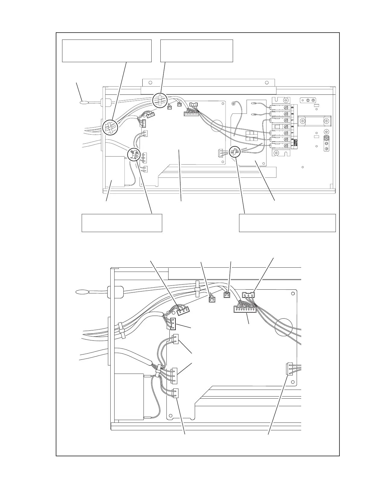
6. Wiring and Parts layout
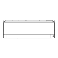
CONTROLLER PCB
BIND
(Wire with connector (For Display))
(Thermistor (Pipe temp.))
(Wire with connector (For Stepping motor))
BIND
(Wire with connector (For Fan motor))
(Wire with connector (For Capacitor ))
BIND
(Wire with connector (For Power Supply PCB))
(Wire with connector (For ACIN ))
BIND
(Wire with connector (For Display))
(Thermistor (Pipe temp.))
(Thermistor (Room temp.))
CN17
(Remocon)
CN8
Thermistor
(Room temp.)
CN7
Thermistor
(Pipe temp.)
CN11
Stepping motor
(Left / Right)
CN10
Stepping motor
(Up / Down)
CN13
(Display)
CN4
(Capacitor)
CN16 (FAN MOTOR)
CN5 (FAN MOTOR)
CN1
(Power Supply PCB)
Power Supply PCB
Capacitor,Plastic
BLACK
WHITE
RED
RED
WHITE
BLACK
Thermistor
(Room temp.)
 Loading...