En-11
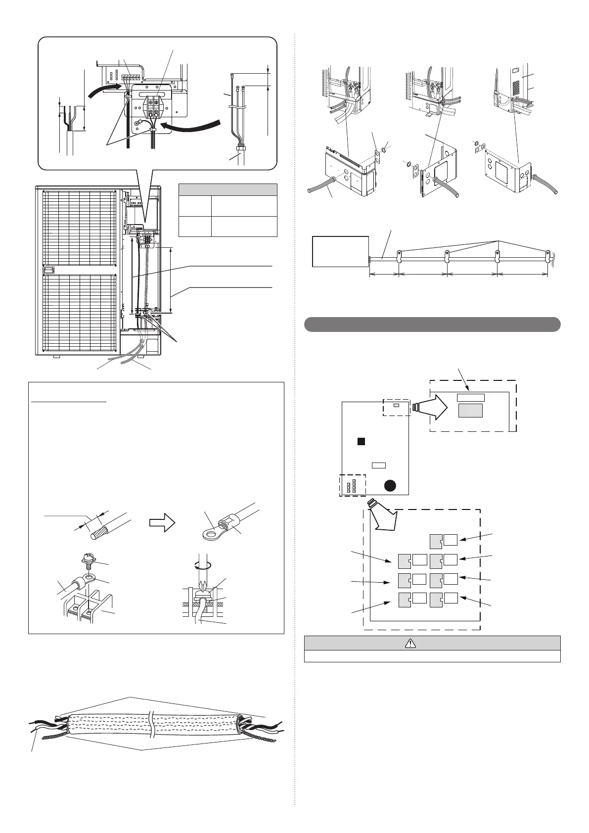
Power supply terminal
Ring terminal (M5)
Transmission terminal (M3)
About 21-5/8 in (550 mm)
Cable tie (accessory)
Conduit (Power supply cable)
Transmission cable
About 20-1/2 in (520 mm)
Cable tie
(accessory)
Conduit
Earth
(ground)
cable
9/16 to 1 in
(15 to 25 mm)
5/16 to 3/8 in
(8~10 mm)
1 to 1-9/19 in
(25~40 mm)
Tightening torque
M3 screw
4.4 to 5.3 lbf·in
(0.5 to 0.6 N·m)
M5 screw
17.7 to 26.5 lbf·in
(2.0 to 3.0 N·m)
How to connect wiring to the terminal
Caution when wiring cable
(1) Use ring terminals with insulating sleeves as shown in the fi gure to connect to the
terminal block.
(2) Securely clamp the ring terminals to the cables using an appropriate tool so that
the cables do not come loose.
(3) Use the specifi ed cables, connect them securely, and fasten them so that there is
no stress placed on the terminals.
(4) Use an appropriate screwdriver to tighten the terminal screws. Do not use a screw-
driver that is too small, otherwise, the screw heads may be damaged and prevent
the screws from being properly tightened.
(5) Do not tighten the terminal screws too much, otherwise, the screws may break.
(6) See the table below for the terminal screw tightening torques.
Strip 3/8 in
(10 mm)
Cable
Screw with
special washer
Ring terminal
Terminal block
Ring terminal
Sleeve
Screw with
special washer
Ring terminal
Cable
Shielding the transmission cable
Connect both ends of the shielded wire of the transmission cable to the earth (ground)
terminal of the equipment or to the earth (ground) screw near the terminal.
Be sure to use one side of a twisted-pair cable when using transmission cable with 2 sets
of twisted-pair cables.
Wind with insulation tape to prevent short circuit
Use one side of the
twisted-pair cable
Connect both ends of shielded wire to earth (Ground).
Installation method of conduit plate
Please fi x the conduit plate (accessory) as shown in the fi gure below.
Front connection
Cable (with conduit)
Conduit plate
lock nut
Lateral connection Rear connection
• Fix the conduit with the supporters as shown below.
Supporter
Conduit (Power supply cable)
Outdoor unit
30 in
(756 mm)
or less
54 in
(1,361 mm)
or less
54 in
(1,361 mm)
or less
54 in
(1,361 mm)
or less
6. 6. External input and external output
6. 6. 1. Terminal position
Base heater
(CN115:Black)
Outdoor unit
PC board
Input 4
(CN134:Red)
Input 3
(CN133:White)
Input 2
(CN132:Green)
Input 1
(CN131:Yellow)
BASE HEATER
CN115 (BLK)
Input 5
(CN135 :
Orange)
PULSE
IN
CN134
CN133
CN132
CN135
CN136
CN137
CN131
EXT.
OUT. 1
EXT.
IN. 4
EXT.
IN. 3
EXT.
IN. 2
EXT.
IN. 1
EXT.
OUT. 2
(ORG)
(RED)
(WHT)
(GRN)
(YEL)
(BLK)
(BLU)
Output 1
(CN136 :
Black)
Output 2
(CN137:
Blue)
CAUTION
Do not bundle the cable for base heater with other cables.
9380545095_IM.indb 119380545095_IM.indb 11 11/17/2015 4:14:27 PM11/17/2015 4:14:27 PM
 Loading...