En-6
Table. A (Wall thickness and pipe material for each diameter)
Outside Diameter
in
(mm)
1/4
(6.35)
3/8
(9.52)
1/2
(12.70)
5/8
(15.88)
3/4
(19.05)
Wall Thickness
*2
in
(mm)
0.032
(0.8)
0.032
(0.8)
0.032
(0.8)
0.039
(1.0)
0.047
(1.2)
Material COPPER
*1
JIS H3300 C1220T-O or equivalent
Please select the pipe size in accordance with local rules.
*1. Allowable tensile stress ≥ 33 N/mm
*2. Endurance pressure of the pipes 609 psi (4.2 MPa)
Table. B (Diameter of piping used between outdoor unit and fi rst separation
tubes or headers)
MODEL
Outdoor
unit cooling
capacity
[Btu]
Diameter of piping [in (mm)]
Between outdoor unit and
the farthest indoor unit < 90
m *3
Between outdoor unit and
the farthest indoor unit ≥ 90
m *3
Liquid pipe Gas pipe Liquid pipe Gas pipe
AOU36RLAVM
36,000 3/8 (9.52) 5/8 (15.88) 3/8 (9.52) 3/4 (19.05)
AOU48RLAVM
48,000 3/8 (9.52) 5/8 (15.88) 3/8 (9.52) 3/4 (19.05)
AOU60RLAVM
60,000 3/8 (9.52) 3/4 (19.05) 3/8 (9.52) 3/4 (19.05)
*3. Pipe Length: “a+f” or “a+p” of “4.1. SYSTEM CONFIGURATION”
Table. C (Diameter of piping used between separation tubes)
Total cooling capacity
of indoor unit [Btu]
Outside diameter [in (mm)]
Separation
tube *4
Header *4
Liquid pipe Gas pipe
x < 36,000 3/8 (9.52) 5/8 (15.88)
UTP-AX054A
UTR-H0906L
UTR-H0908L
36,000 ≤ x3/8 (9.52)3/4 (19.05)
*4. For the installation method, please refer to the installation manuals for indoor unit,
separation tubes or headers.
If pipe diameter Table C > Table B , select pipe size from Table B.
“Total cooling capacity of indoor unit” is the total value for the cooling capacity of indoor unit
connected downstream.
Use a standard separation tube for pipe branching. Do not use a T tube as it does not
separate the refrigerant evenly.
Table. D (Diameter of piping used between separation tube and indoor unit)
Cooling capacity of indoor unit
[Btu]
Outside diameter [in (mm)]
Liquid pipe Gas pipe
7,500 / 9,500 / 12,000 / 14,000 1/4 (6.35) 1/2 (12.70)
18,000 / 24,000 / 30,000
3/8 (9.52)
5/8 (15.88)
36,000 / 48,000 / 60,000 *5 3/4 (19.05)
*5. If pipe diameter Table D > Table C , using of pipe size from Table C is preferable.
(Use reducer to change the diameter of connection pipe.)
4. 3. Protection of pipes
Location Working period
Protection method
Outdoor
1 month or more Pinch pipes
Less than 1 month Pinch or tape pipes
Indoor — Pinch or tape pipes
• Protect the pipes to prevent the entry of moisture and dust.
• Especially pay attention when passing the pipes through a hole or connecting the end of
a pipe to the outdoor unit.
5. PIPE INSTALLATION
5. 1. Brazing
CAUTION
If air or another type of refrigerant enters the
refrigeration cycle, the internal pressure in
the refrigeration cycle will become abnormally
high and prevent the unit from exerting its full
performance.
Pressure regulating valve
Cap
Nitrogen gas
Brazing area
Apply nitrogen gas while brazing the pipes.
Nitrogen gas pressure: 2.9 psi (0.02 MPa)
(= pressure felt suffi ciently on the back of your
hand)
If a pipe is brazed without applying nitrogen gas, it will create an oxidation fi lm.
This can degrade performance or damage the parts in the unit (such as the compressor
or valves).
Do not use fl ux to braze pipes. If the fl ux is the chlorine type, it will cause the pipes to
corrode.
In additio
n, if the fl ux contains fl uoride, it will affect the refrigerant piping system due to
deterioration of refrigerant oil.
For brazing material, use phosphor copper that does not require fl ux.
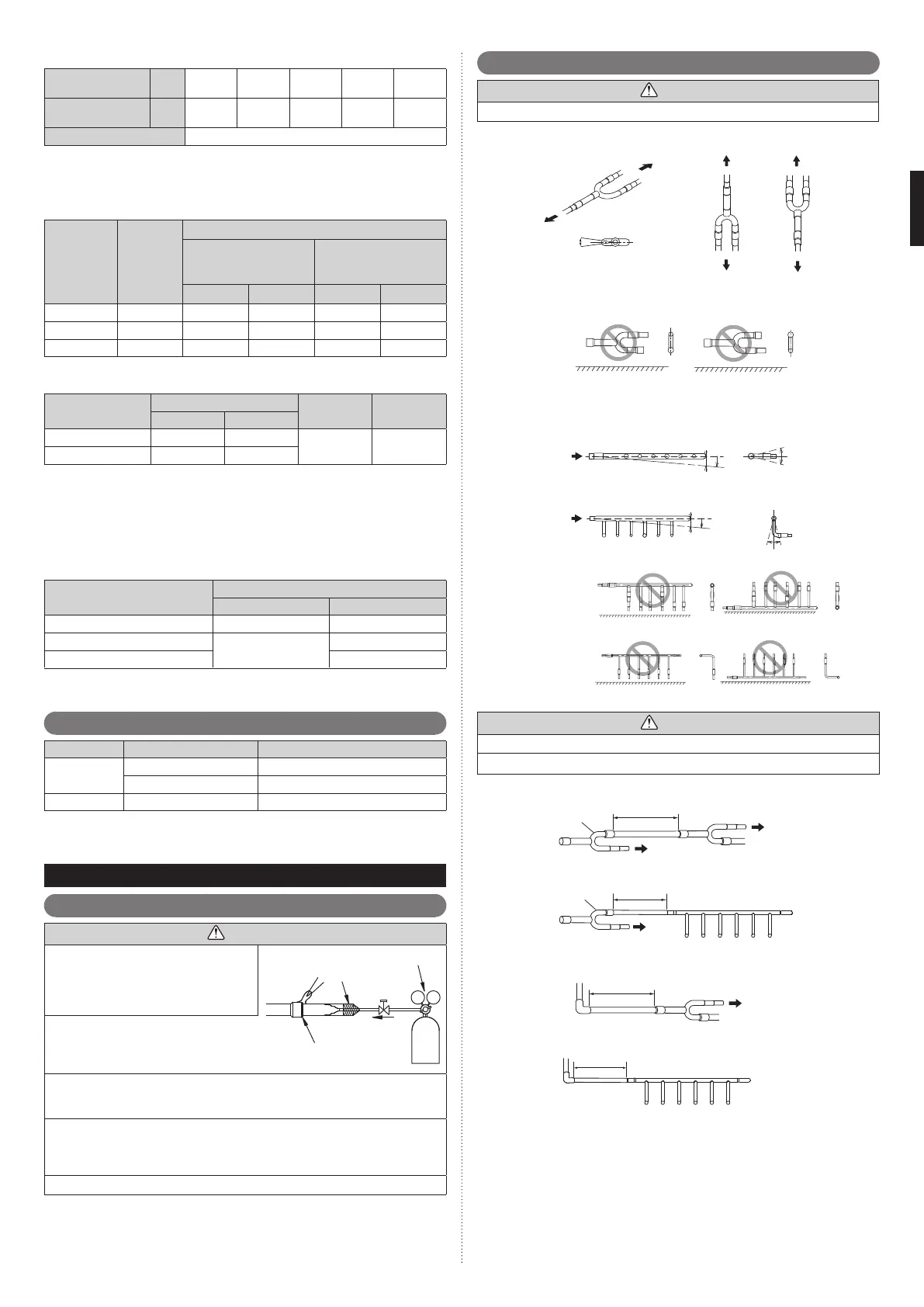
5. 2. Indoor unit pipe connections
CAUTION
For details, refer to the Installation Instruction Sheet of each part.
Separation tube
A
B
A
B
B
A
GOOD
Horizontal
Vertical
Horizontal line
or
± 15°
A : Outdoor unit or Refrigerant branch kit
B : Indoor unit or Refrigerant branch kit
PROHIBITED
Header
C
H
1
A
1
B
1
D
H
2
A2
B2
GOOD
Horizontal line
Horizontal
line
VIEW D
VIEW C
Horizontal
line
Horizontal
line
Gas pipe
Liquid pipe
Outdoor
unit side
Outdoor
unit side
H
1
= 0 to 3/8 in
(0 to 10 mm)
H
2
= 0 to 3/8 in
(0 to 10 mm)
PROHIBITED PROHIBITED
(α
1
: 0° to 1°)
β
1
: -10° to 10°
(α
2
: 0° to 1°)
β
2
: -10° to 10°
CAUTION
Do not connect a separation tube after a header.
Leave the distance 2 ft (0.5 m) or more for straight part to branch tube and header.
Main pipe
2 ft
(0.5 m) or more
To ind oor uni t
To ind oor uni t
To ind oor uni t
Main pipe
2 ft
(0.5 m) or more
To ind oor
unit
Separation tube
or
Header
2 ft
(0.5 m) or more
2 ft
(0.5 m) or more
To ind oor uni t
or
Header
Separation tube
To ind oor
unit
9380545095_IM.indb 69380545095_IM.indb 6 11/17/2015 4:14:25 PM11/17/2015 4:14:25 PM
 Loading...