EasyManua.ls Logo

Fujitsu AOU48RLXFZ1 User Manual

Fujitsu AOU48RLXFZ1
38 pages
To Next Page IconTo Next Page
Page #1 background imageLoading...
Page #1 background image
EnglishFrançaisEspañol
AIR CONDITIONER
OUTDOOR UNIT
INSTALLATION MANUAL
For authorized personnel only.
PART No. 9379069342-02
Contents
1. SAFETY PRECAUTIONS …………………………… 2
2. ABOUT THE PRODUCT
2.1. Precautions for using R410A refrigerant ……… 4
2.2. Special tools for R410A ………………………… 4
2.3. Accessories ……………………………………… 4
2.4. Optional parts …………………………………… 5
2.5. Operating range ………………………………… 5
2.6. Systemconguration …………………………… 6
3. INSTALLATION WORK
3.1. Selecting an installation location ……………… 7
3.2. Drain installation ………………………………… 8
3.3. Installation dimensions ………………………… 8
3.4. Transportation of the unit …………………… 10
3.5. Installation of the unit ………………………… 10
4. SYSTEM CONFIGURATION
4.1. Piping limitation and Pipe size ……………… 11
5. PIPE INSTALLATION
5.1. Opening a knockout hole …………………… 13
5.2. Separation tube connection ………………… 14
5.3. Flare connection (pipe connection) ………… 14
6. ELECTRICAL WIRING
6.1. The precautions of electrical wiring ………… 17
6.2. Knockout hole ………………………………… 18
6.3. Electrical requirement ………………………… 18
6.4. Unit wiring ……………………………………… 19
6.5. Wiring method ………………………………… 20
6.6. Connecting of wiring ………………………… 21
7. PIPE INSTALLATION II
7.1. Sealing test …………………………………… 22
7.2. Vaccum process ……………………………… 23
7.3. Additional charging …………………………… 24
7.4. Refrigerant recovery method
……………… 25
7.5. Installing insulation …………………………… 26
7.6. Filling with putty ……………………………… 26
8. FIELD SETTING
8.1. Field setting switches ………………………… 27
8.2. Function settings ……………………………… 28
9. TEST OPERATION
9.1. Check run ……………………………………… 30
9.2. TEST RUN …………………………………… 33
9.3. Conrmingtheoperationofindoorunit …… 35
10. EXTERNAL INPUT & OUTPUT
10.1. Fitting cable (option parts) …………………… 35
10.2. External input ………………………………… 35
10.3. External output ………………………………… 37
11. LED Display
11.1. Normal operation mode ……………………… 38
11.2. Error display mode …………………………… 38
9379069342-02_IM.indb 1 17/5/2556 11:49:25
Question and Answer IconNeed help?

Do you have a question about the Fujitsu AOU48RLXFZ1 and is the answer not in the manual?

Fujitsu AOU48RLXFZ1 Specifications

General IconGeneral
BrandFujitsu
ModelAOU48RLXFZ1
CategoryAir Conditioner
LanguageEnglish

Summary

Safety Precautions for Air Conditioner Installation

General Safety Guidelines

Essential safety advice for installation, operation, and servicing of the air conditioner.

Special Precautions for Installation and Operation

Covers specific safety measures for wiring, transportation, installation, refrigerant handling, and maintenance.

About the Product

R410A Refrigerant Precautions and Tools

Key safety and handling precautions for R410A refrigerant, including special tools required.

Included Accessories and Optional Parts

Details included accessories and lists optional parts specific to R410A refrigerant systems.

Operating Range and System Configuration

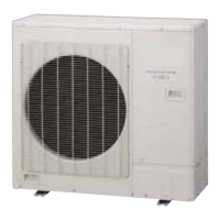
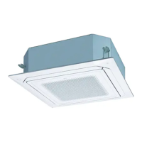
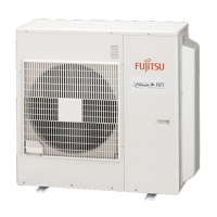
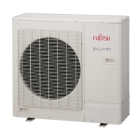
Specifies permissible operating conditions and illustrates the system configuration.

Installation Work Procedures

Installation Location Selection

Guidelines for choosing an appropriate and safe location for the outdoor unit installation.

Drain Installation

Instructions for proper drain pipe installation and precautions for cold weather.

Installation Dimensions and Spacing

Specifies required installation space and dimensions for single and multiple outdoor units.

Unit Transportation and Installation

Safety precautions for unit transportation and securing the outdoor unit to its foundation.

System Configuration and Piping

Piping Limitations and Pipe Sizing

Defines pipe length limitations and specifies appropriate pipe sizes for system configuration.

Pipe Installation

Knockout Hole Creation

Procedure for creating knockout holes for pipe entry and precautions for panel protection.

Separation Tube Connection

Guidance on connecting separation tubes for refrigerant piping branches.

Flare Connection Procedures

Instructions for making flare connections on refrigerant pipes, including flaring, bending, and connection.

Valve Handling Precautions

Procedures for safely operating and securing the unit's valves.

Electrical Wiring

Electrical Wiring Safety Precautions

Crucial safety warnings and precautions for electrical wiring installation.

Knockout Holes and Electrical Requirements

Procedure for knockout holes and specifications for electrical requirements, cables, and breakers.

Unit Wiring and Connection Methods

Step-by-step guide for connecting wires to the terminal block and wiring examples.

Connecting Wiring and Conduit Plates

Details on connecting wires, securing cables, and installing conduit plates.

Pipe Installation II

Sealing Test and Vacuum Process

Procedures for performing a sealing test and evacuating the refrigerant system using a vacuum pump.

Refrigerant Charging and Recovery

Methods for adding and recovering refrigerant, including calculation and procedures.

Pipe Insulation and Putty Application

Guidelines for pipe insulation and filling holes with putty for protection.

Field Setting

Field Setting Switches and Function Settings

Details on setting outdoor unit functions using switches and the overview of available settings.

Setting Method Navigation

Detailed procedure for navigating menus and setting functions using buttons.

Test Operation

Check Run Procedures and Confirmations

Procedure for performing a check run, including confirmations and operational restrictions.

Check Run Operating Procedure

Step-by-step instructions for initiating and conducting the check run.

Error Display Interpretation

Explains how to interpret error codes displayed on the 7-segment display and LED lamps.

Test Run Procedures and Settings

Details on performing test runs, including pre-checks, methods, and setting controls.

External Input & Output

External Input/Output Cable Fitting and Input Functions

Instructions for fitting cables and details on external inputs for controlling unit functions.

Specific External Input Modes

Explains Low noise, Priority, Peak cut, and Stop operation modes via external input.

External Output Signals and Base Heater

Information on external outputs for error/compressor status and the base heater function.

LED Display

Normal Operation LED Indicators

Table showing LED indicators for normal operation modes.

Error Display Mode and Code Interpretation

Explanation of error codes and how to interpret them via 7-segment display and LEDs.

Related product manuals