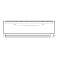
Knockout hole6. 2.
CAUTION
Be careful not to deform or scratch the panel while opening the knockout holes.•
When cables are routed from the unit, a protection sleeve for the conduits can be inserted at the knockout hole.•
If you do not use a wire conduit, be sure to protect the wires to prevent the edge of the knockout hole from •
cutting the wires.
It is recommended to apply anti-rust paint to the edge of the knockout hole.•
Knock out holes are provided for wiring. (Fig. A)•
Knock out holes are provided 2 each in the same size in front, lateral and rear sides. (Fig. B) •
Fig. A Fig. B
Service panel
Front connection Lateral connection Rear connection
Electrical requirement6. 3.
CAUTION
Besuretoinstallabreakerofthespeciedcapacity.
Regulation of cables and breaker differs from each locality, refer in accordance with local rules.
Voltage rating 1Φ208/230V(60Hz)
Operating range 187-264V
Cable Cable size *
1)
Remarks
Power supply cable 8AWG 2 cable + Ground, 1 Ø 208/230V
Connection cable 14AWG 3 cable + Ground, 1 Ø 208/230V
Selected sample: Select the correct cable type and size according to the country or region’s regulations. 1)
Max. wire length: Set a length so that the voltage drop is less than 2%. Increase the wire diameter when the wire
length is long.
Breaker Specication *
2)
Circuit breaker (MOCP) *4) Current : 40 (A)
Earth leakage breaker Leakage current : 30mA 0.1sec or less *3)
Selecttheappropriatebreakerofthedescribedspecicationaccordingtothenationalorregionalstandards. 2)
Select the breaker that enough load current can pass through it. 3)
MOCP: Maximum Over Current Protection 4)
 Loading...
