En-3
2.2. Special tools for R410A
Tool name Contents of change for R22 tool
Gauge
manifold
Pressure is huge and cannot be measured with a conventional gauge.
To prevent erroneous mixing of other refrigerants, the diameter of each
port has been changed.
It is recommended to use a gauge manifold with a high pressure display
range 500 microns to 768 psi (-0.1 to 5.3 MPa) and a low pressure
display range 500 microns to 551 psi (-0.1 to 3.8 MPa).
Charging
hose
To increase pressure resistance, the hose material and base size were
changed.
Vacuum
pump
A conventional vacuum pump can be used by installing a vacuum pump
adapter.
• A conventional vacuum pump can be used by installing a vacuum
pump adapter.
• Be sure that the pump oil does not back flow into the system. Use one
capable for vacuum suction of 500 microns (-100.7 kPa).
Gas leakage
detector
Special gas leakage detector for HFC refrigerant R410A.
2.3. Accessories
Use connecting parts as required.
Do not throw away the connecting parts until the installation has been complete.
Name and shape Q’ty Application
Specifications
manual
1—
Installation manual
1
(This manual)
Cable tie
4
For binding power cable and
transmission cable
Reducer
1
For connecting gas pipe
(For 60 model)
2.4. Combinations
The number of indoor units that can be connected are as follows:
Model
Outdoor unit cool-
ing capacity [BTU]
Maximum connect-
able indoor units
Connectable total
indoor unit capacity
ratio [%]
AOU36RLAVM4 36,000 9
50 to 150 (*1)AOU48RLAVM4 48,000 12
AOU60RLAVM4 60,000 15
*1: The conditions may differ depending on the connected indoor unit. For detailed infor-
mation, refer to the Design & Technical manual.
2.5. Optional parts
CAUTION
The following parts are optional parts specific to R410A refrigerant.
Do not use parts other than those listed below.
2.5.1 Separation tube kit and Header
Separation tube and header uses
the following parts. A header is
used for connecting the indoor
units.
Separation
tube
Header
3-6 Branches 3-8 Branches
UTP-AX054A UTR-H0906L UTR-H0908L
2.5.2 External connect kit
Model Usage
UTY-XWZXZ6
For External input (CN131, CN132, CN133, CN134)
For External output (Error status / CN136) (Operation status / CN137)
UTY-XWZXZF
For External input (CN135)
2.6. About unit of the length
This product is manufactured to metric units and tolerances. United States customary
units are provided for reference only. In cases where exact dimensions and tolerances are
required, always refer to metric units.
3. INSTALLATION WORK
Please obtain the approval of the customer when selecting the location of installation and
installing the main unit.
3.1. Selecting an installation location
WARNING
Install the unit in a location that can withstand its weight, and where it will not topple or
fall.
Calculate the proper refrigerant concentration if you will be installing it in an enclosed
location.
Total amount of replenished refrigerant
in refrigerant facility [lb. (kg)]
≤
Refrigerant concentration [lb/Mcf (kg/m³)]
[25 lb/Mcf (0.39 kg/m³)]
Capacity of smallest room where unit
is installed [Mcf (m³)]
If the results of the calculation exceed the concentration limit, increase the room surface
area or install a ventilation duct.
CAUTION
Please install the outdoor unit without slant. (within 3 degrees)
Install this unit in a location with good ventilation.
If the unit must be installed in an area within easy reach of the general public, install as
necessary a protective fence or the like to prevent their access.
Install the unit in an area that would not inconvenience your neighbors, as they could be
affected by the airflow coming out from the outlet, noise, or vibration.
If it must be installed in proximity to your neighbors, be sure to obtain their approval.
If the unit is installed in a cold region that is affected by snow accumulation, snow fall, or
freezing, take appropriate measures to protect it from those elements.
To ensure a stable operation, install inlet and outlet ducts.
Install the unit in an area that would not cause problems even if the drain water is
discharged from the unit. Otherwise, provide drainage that would not affect people or
objects.
Install the unit in an area that has no heat sources, vapors, or the risk of the leakage of
flammable gas in the vicinity.
Install the unit in an area that is away from the exhaust or vent ports that discharge
vapor, soot, dust, or debris.
Install the indoor unit, outdoor unit, power supply cable, transmission cable and remote
control cable at least 40 in (1 m) away from a television or radio.
The purpose of this is to prevent TV reception interference or radio noise. (Even if they
are installed more than 40 in (1 m) apart, you could still receive noise under some
signal conditions.)
Keep the length of the piping of the indoor and outdoor units within the allowable range.
For maintenance purposes, do not bury the piping.
3.2. Space requirement
CAUTION
Provide sufficient space requirement, such as transportation route, maintenance space,
ventilation space, refrigerant piping space, and passageways.
Pay attention to the specifications of the space requirement as shown in the figure. If
the unit is not installed according to specifications, it may cause short circuit or poor
performance. The unit may be prone to lapse into non-operation due to high pressure
protection.
When there is a wall in front of the unit, provide a space of 20 in (500 mm) or more as
maintenance space.
When there is a wall at the right side of the unit, provide a space of 4 in (100 mm) or
more as maintenance space.
An outdoor temperature of 95 °F (DB) (35 °C (DB)) in air-conditioned operation is as-
sumed for the space requirement in this item. If the outdoor temperature exceeds 95 °F
(DB) (35 °C (DB)) and the outdoor unit is operating at a load exceeding its rated ability,
provide a larger inlet space.
If you are installing more outdoor units than indicated here, please ensure sufficient
space or consult your distributing agent as it may affect the performance due to short
circuit and other problems.
Consider the transportation route, clearance requirement, maintenance space, and ac-
cess, and install the unit in a location with sufficient space for the refrigerant piping.
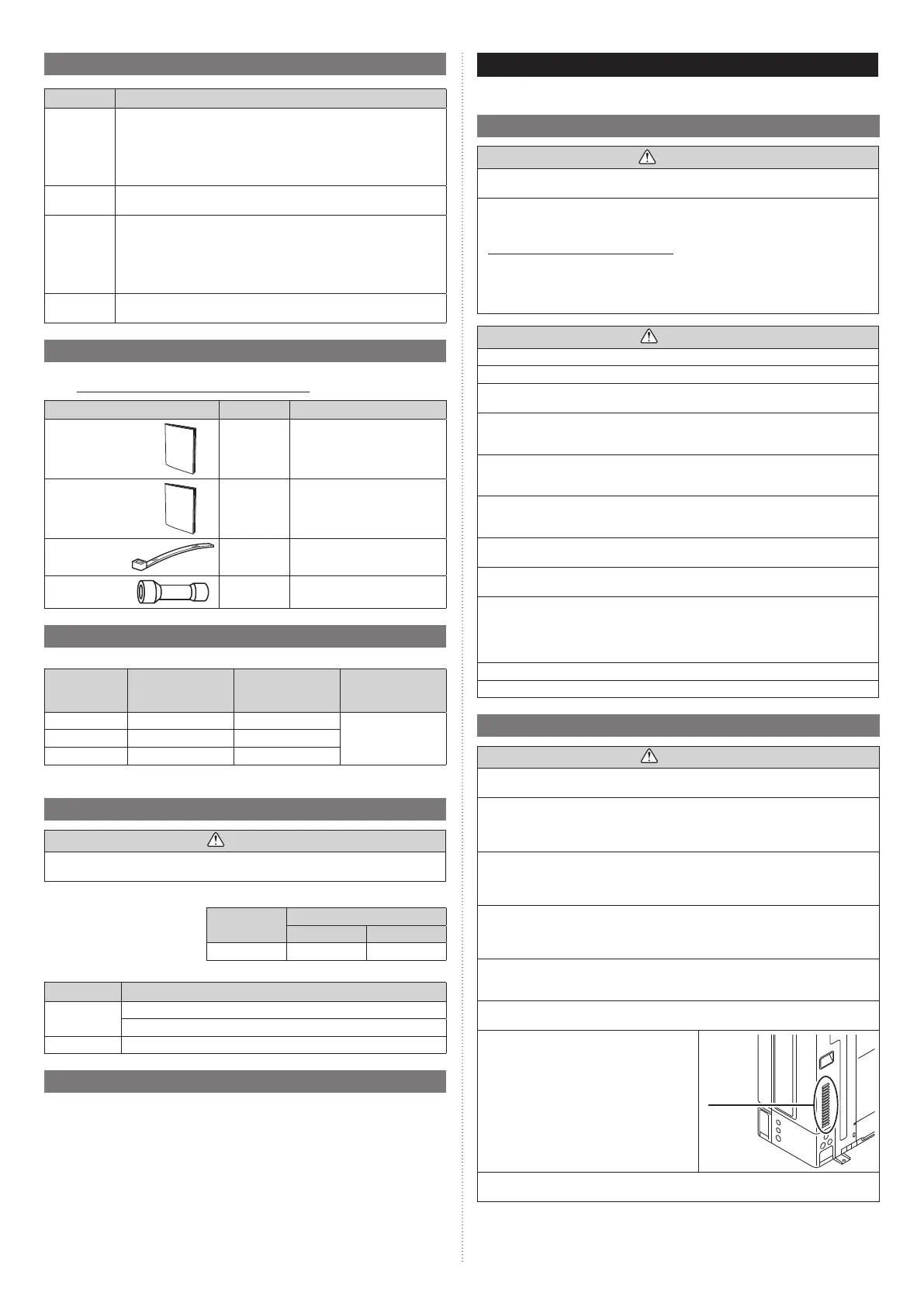
Observe the space requirements that are
shown in the figures.
Keep the same space at rear air intake.
Provide the same space for the air intake at the
rear of the outdoor unit.
If the installation is not performed according to
the specifications, it could cause a short circuit
and result in a lack of operating performance.
As a result, the outdoor unit might easily be
stopped by high-pressure protection.
Air intake
Rear view
Installation methods not shown in the following examples are not recommended. Perfor-
mance may drop significantly.
9380545361-02_3L.indb 39380545361-02_3L.indb 3 2022/10/26 14:59:362022/10/26 14:59:36
 Loading...