10-3. Function settings on wired remote controller
By using some components on the wired remote controller, you can change the function settings re-
lated on the remote controller.
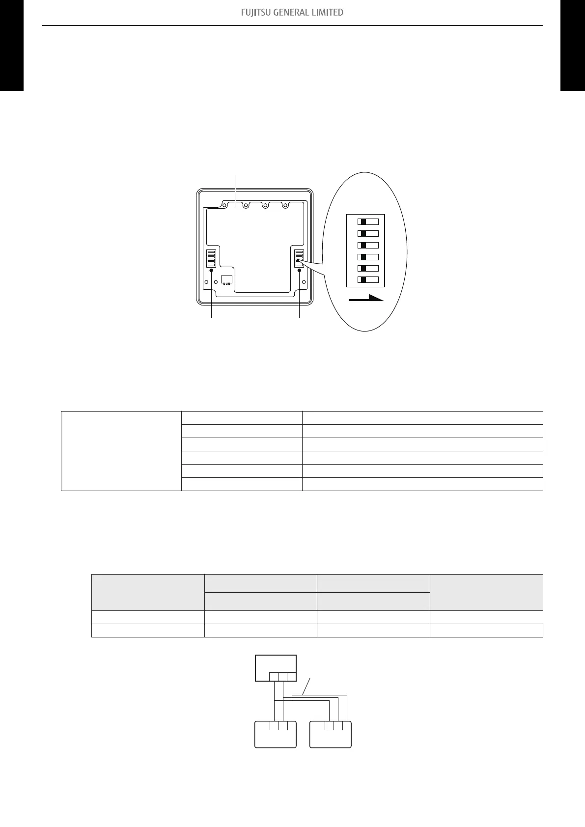
¢ Component location
Components on the wired remote controller used for the function settings are located as shown
in the following figure.
NOTE:
Do not use DIP switch 2.
ON
ON
OFF
1
2
3
4
5
6
Front case (back side)
DIP switch 2
(All switches are fixed at OFF.)
DIP switch 1
¢ DIP switch setting
By switching each slide switch on the DIP switch 1, you can change the function settings for the
remote controller.
DIP switch 1
SW1 Setting change prohibited*
SW2 Dual remote controller setting
SW3 Setting change prohibited*
SW4 °F / °C switch
SW5 Setting change prohibited*
SW6 Memory backup setting
*: Switches are fixed at OFF initially.
• SW2: Dual remote controller setting
Number of remote controller can be changed.
Number of remote
controller
Primary unit Secondary unit
Factory setting
SW2 SW2
1 (Normal) OFF ― ♦
2 (Dual) OFF ON
1 231 23
1 2 3
Indoor unit
Primary unit
Secondary
unit
Remote controllers
Remote controller cable
- 40 -
10-3. Function settings on wired remote controller 10. Function settings
CASSETTE TYPE
AUU09-18RLF
CASSETTE TYPE
AUU09-18RLF
 Loading...