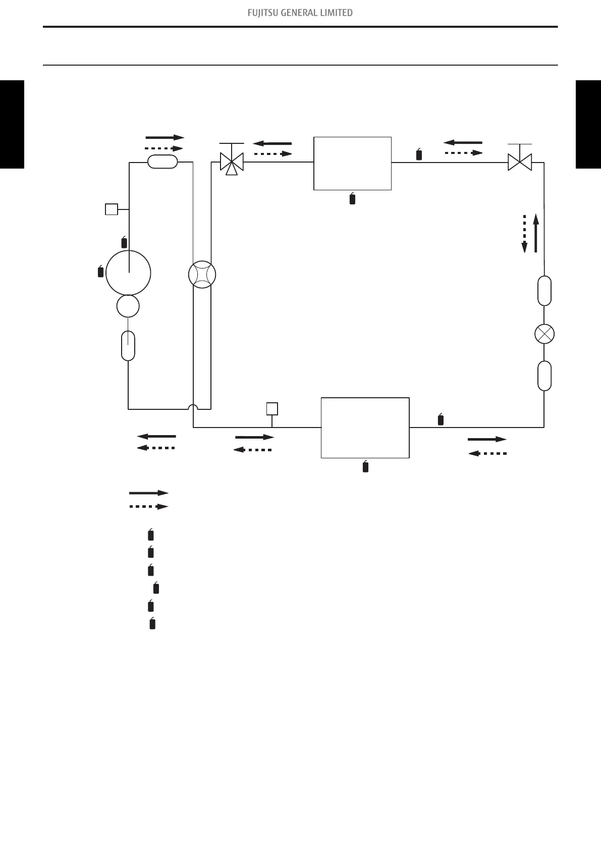
6. Refrigerant system diagrams
6-1. Models: AOU24RGLX and AOU30RGLX
2-Way
valve
Strainer
Strainer
3-Way
valve
Muffler
4-Way valve
Expansion valve
Heat exchanger
( INDOOR )
Heat exchanger
( OUTDOOR )
Co
mpre
s
so
r
: Cooling
: Heating
Pressure
switch
Su
b
-accumulator
Th
C
Th
R
Th
D
Th
PI
Th
O
Th
HO
Th
C
: Thermistor (Compressor temperature)
: Thermistor (Discharge temperature)
: Thermistor (Outdoor temperature)
: Thermistor (Heat exchanger Out temperature)
Th
D
Th
O
Th
HO
: Thermistor (Room temperature)
: Thermistor (Pipe temperature)
Th
R
Th
PI
Pressure
check valve
6-1. Models: AOU24RGLX and AOU30RGLX - (02-23) - 6. Refrigerant system diagrams
TECHNICAL DATA
AND PARTS LIST
TECHNICAL DATA
AND PARTS LIST
 Loading...

