2.9.6 Electrical connections on the hydraulic
module side
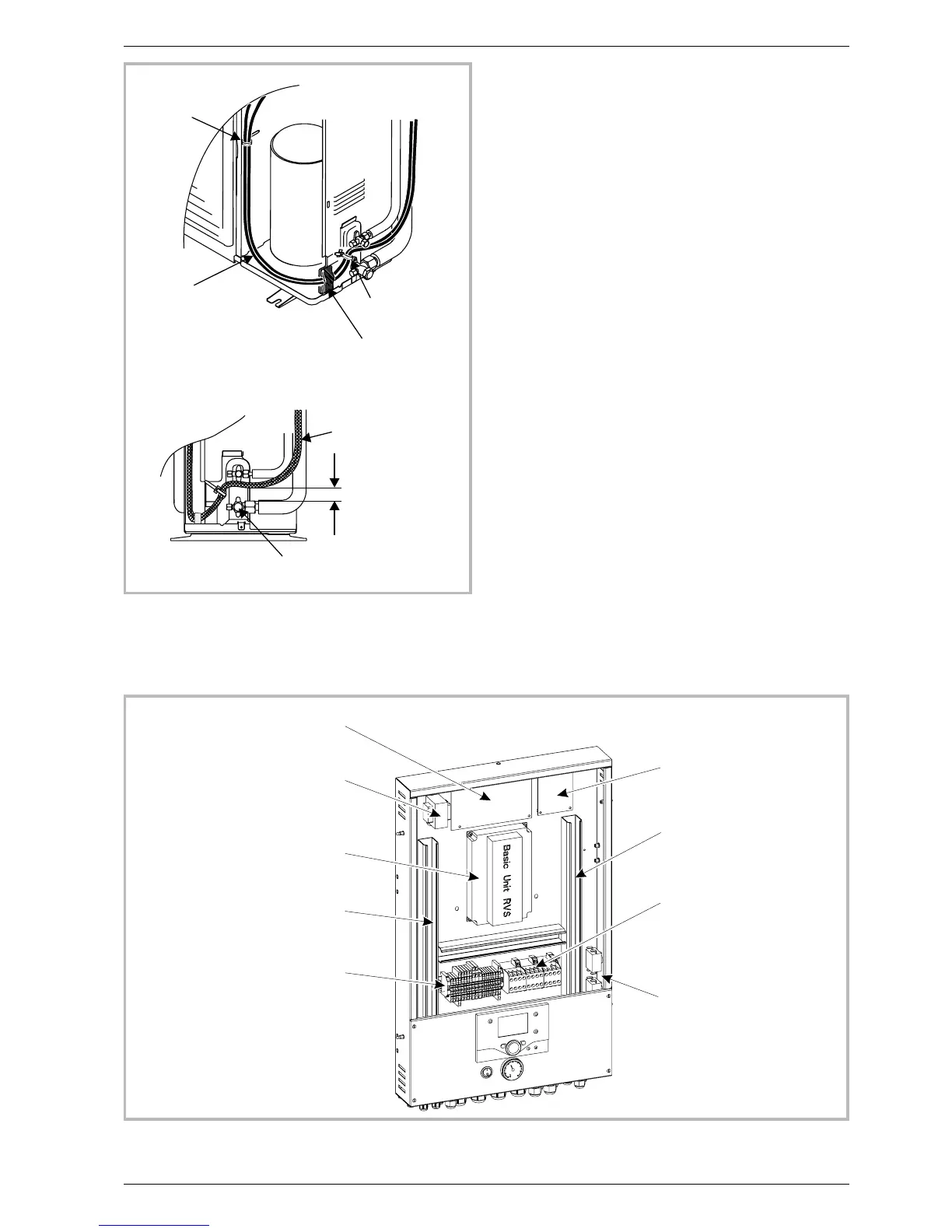
Access to the connection terminals
-
Remove the front panel (2 screws) (fig. 16, p. 17)
-
Remove the cover of the electric box.
-
Make the connections in accordance with the
diagram(s) Fig. 37.
Do not place the sensor lines and the sector supply
lines in parallel in order to avoid causing inadvertent
interference due to voltage points in the sector
supply.
Ensure that all the electrical cables are housed in the
spaces provided for this purpose inside the lifting
handles.
Installation and operating manual “1350-EN” 27
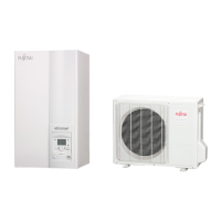
Heat pump, Split, single service
Release
Cable clamp
Cable clamp
Flexible
insulation plate
Cables
(supply and
interconnection)
Cables
Gas valve
Figure 35 - Finalisation of connection
to outside unit
Transformer
Power card
Interface card
Heat pump regulator
Terminal blocks
Power relay
Cable grommet (Power)
Cable grommet (low voltage)
Safety thermostat
Figure 36 - Access to hydraulic model electric box and description
 Loading...