2.9.5
Electrical connections on outside unit
side
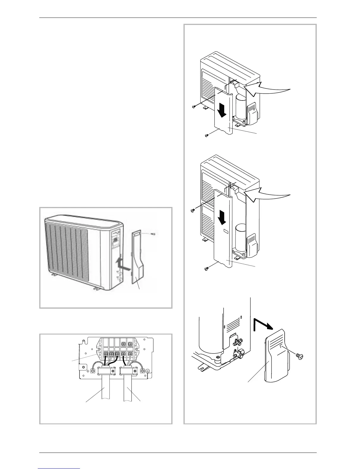
Access to the connection terminals
•
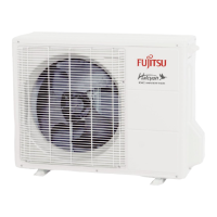
Model 050, 065, 080
-
Remove the cap (figure 32).
•
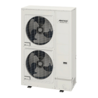
Model 095, 128, 155
-
Remove the front panel
-
Remove the cap (figure 34).
Make the connections in accordance with the
diagram(s) Fig. 33.
Use cable clamps to prevent the conductors from
being disconnected accidentally.
Fill in the space where the cables enter the outside
unit with the insulating plate (fig. 35).
26 Installation and operating manual “1350-EN”
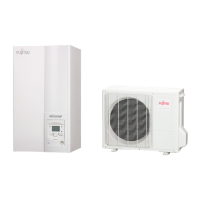
Heat pump, Split, single service
Remove the cap
(1 screw)
Figure 32 - Access to outside unit’s terminal block
(model 050, 065, 080)
General electrical
supply
Terminal
block
Interconnection
between the external unit
and the hydraulic module
Figure 33 - Connections to outside unit’s terminal
block
Remove the front panel
(2 screws)
Remove the front panel
(2 screws)
Remove
the cap (1 screw)
Figure 34 - Access to outside unit’s terminal block
(model 095, 128, 155)
 Loading...