
M
Michael LoganAug 2, 2025
Why Fujitsu Waterstage WOYA060LFCA has no connection?
- AAlexandra RichardsonAug 2, 2025
The Fujitsu Heat Pump might not be connecting due to failure to comply with the room thermostat's polarity.
Why Fujitsu Waterstage WOYA060LFCA has no connection?
The Fujitsu Heat Pump might not be connecting due to failure to comply with the room thermostat's polarity.
How to configure 2e zone sensor on Fujitsu Waterstage WOYA060LFCA Heat Pump?
If the 2e zone sensor is not configured on your Fujitsu Heat Pump (if using a 2nd circuits kit), set the parameter 5700 to 2, 4, or 6 using BX31.
Manual number, date, language options.
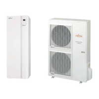
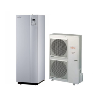
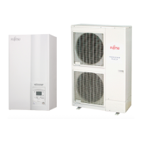
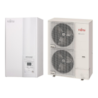
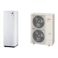
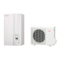
Air to Water Heat Pump, Split system.
Manual for professionals, for future consultation.
Lists items included in the unit package.
Explains terms like Split, Air/Water, Inverter, COP.
Lists technical specifications of the heat pump.
Professional installation and maintenance guidelines.
Procedures for safe receipt and handling of the unit.
Ensuring correct containment and preventing contamination.
Lists accessories provided with the units.
Rules, precautions, and procedures for handling refrigerant.
Procedures for connecting the heating circuit and water volume.
Requirements for electrical supply and safety.
Guidelines for wiring, polarity, and grounding.
Lists optional kits for extended functionality.
Describes the functions and capabilities of the heat pump.
Heat output, power absorbed, and COP values.
Supply voltage, current, power ratings.
Operating pressure, flow rates.
Temperature ranges for operation.
Pipe diameters, refrigerant charge, pressure.
Shows external dimensions and mounting points.
Shows external dimensions and mounting points.
Illustrates external dimensions and connection points.
Shows hydraulic pressure vs. flow rate for variable systems.
Shows hydraulic pressure vs. flow rate for constant systems.
Resistance values for outdoor temperature sensor.
Resistance values for flow and return sensors.
Resistance of sensors in the outdoor unit at different temperatures.
Diagram identifying parts of the outdoor unit.
Diagram identifying parts of the outdoor unit.
Diagram identifying parts of the outdoor unit.
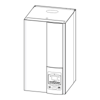
Diagram identifying parts of the hydraulic unit.
How the heat pump transfers energy from air to water.
Control functions for heating, DHW, and options.
Safety features like frost protection.
How DHW is heated and controlled.
DHW priority over heating and control functions.
Illustrates energy flow and components.
Requirements for professional installation and maintenance.
Procedures for receiving and checking the unit.
Guidelines for safely transporting and moving the unit.
Precautions to prevent contamination and maintain circuit integrity.
Lists accessories for outdoor and hydraulic units.
Connecting refrigerant pipes with protective caps and insulation.
Specifies pipe sizes and minimum/maximum distances.
Requirement for minimum refrigerant pipe length for operation.
Guidelines for location, weather protection, and airflow.
Required spacing around the outdoor unit for airflow.
Conditions for using wall brackets and preferred ground mounting.
Installation of drain pan, hose, and trace heating.
Location choice, room ventilation, and space for maintenance.
How to fix the support and mount the unit.
Handling refrigerants, tool requirements, and oil types.
Bending and flaring techniques for pipes.
Brazing methods and insulation requirements for pipes.
Table of pipe sizes and lengths for different models.
Procedures for checking connections using nitrogen.
Table of torque values for nuts and plugs.
Step-by-step guide for creating vacuum.
Detailed vacuum creation using a manifold and gauge.
Checking for leaks after gas filling.
How to calculate and add refrigerant charge based on distance.
Steps for adding extra refrigerant charge.
Steps to collect refrigerant from the outdoor unit.
Trade practices, sealants, and glycol usage.
Connecting pipes, union connectors, and hoses.
Cleaning the heating system before connection.
Pipe sizing and connection torque.
Steps for filling the system with water and removing air.
How the pump varies manometric height based on flow.
How the pump maintains constant manometric height.
Explains LED status for pump operation and errors.
Shows pump settings for variable and constant pressure.
Troubleshooting steps for blocked pumps.
Proper method for connecting wires to terminals.
How to connect to control boards.
Method for connecting wires to spring terminals.
Wiring diagram showing connections between units and power supply.
Cable size and breaker size for outdoor unit.
Cable specifications for connecting units.
Cable size and breaker for electrical back-ups.
Steps to access terminals for specific models.
Steps to access terminals for Comfort 10 model.
Steps to access terminals on the hydraulic unit.
Ensuring correct connection of communication cables.
Connecting electrical supply for backup heaters.
Instructions for connecting boiler option.
Instructions for second circuit and regulation kits.
Instructions for DHW tank connection.
Connecting for tariff control and power shedding.
Connecting external fault signals.
Diagram showing components within the electric box.
Wiring for terminal blocks and power relays.
Wiring for accessories and options like sensors and thermostats.
Placement and connection of the outdoor temperature sensor.
Installation of optional room sensors and controls.
Steps to follow before and during initial power-up.
Pairing and configuring a wireless room thermostat.
Diagram of the main user interface, remote, and thermostat.
Explains symbols and codes shown on the display.
Adjusting heating temperature based on outdoor conditions.
Adjusting the heating curve offset (parameter 721).
How to adjust settings based on user feedback.
Overview of user, commissioning, and engineer access levels.
Steps for navigating menus and adjusting parameters.
Default settings for different emitter types.
Setting time, date, and summer time.
Language, info, locking, and direct setting options.
Programming heating/cooling periods for circuit 1.
Setting domestic hot water heating schedules.
Configuring holiday periods for heating circuits.
Setting comfort and reduced temperatures.
Setting the minimum temperature for frost protection.
Parameters for heating curve slope and offset.
How room temperature affects settings.
Parameters for optimum start and stop times.
Setting cooling modes and temperatures.
Parameters for summer compressor operation.
Parameters for heating adjustment for the second circuit.
Parameters for cooling circuit 2 operation.
Settings for DHW heating modes and temperatures.
DHW release controls and legionella cycle settings.
Settings for compressor and pump operation times.
Settings for unit switch-off and locking times.
Display of energy consumption for heating, DHW, and cooling.
Setting parameter for compressor electrical power.
Settings for DHW charging and boiler integration.
Settings for DHW temperature and release.
Choosing pre-defined installation setups.
Configuring heating/cooling circuits and DHW control.
Configuring inputs for various functions.
Configuring inputs for utility lock, tariffs, and external faults.
Setting contact type (NC/NO) for inputs.
Settings for sensor readings and setpoint compensation.
Resetting sensors, parameters, and accessing system info.
Settings for maintenance intervals and resets.
Configuring emergency operation and function types.
Testing relays and outputs for correct operation.
Testing outputs and sensor readings.
Checking input signals and operational states.
Checking compressor and pump operation status.
Diagnosing temperature and flow issues.
Checking outdoor and room temperature readings.
Diagnosing pump and mixer valve operation.
Checking the status of various relay outputs.
Hydraulic diagram for a single heating circuit setup.
Electrical diagram for outdoor units.
Shows connections to interface board, controller, and power.
Lists error numbers, descriptions, locations, and operation status.
Lists various operational data shown on the display.
Procedures for checking hydraulic system pressure and safety valves.
Cleaning heat exchanger, checking fan and drain.
Annual checks for refrigerant circuits (for >10kW models).
Checking cable connections and electronic boards.
Checks to perform before powering on the unit.
Checks to perform on the outdoor unit after startup.
Checks to perform on the hydraulic unit after startup.
Checks and adjustments for room control settings.
Settings for language, date, and boiler backup.
Configuration parameters for heating circuits.
Settings for DHW and cooling functions.
List of fault codes and their meanings.
Fields for recording unit details and installer data.
Fields for recording operating voltage, current, and temperatures.
Fields for recording hydraulic system parameters.
Recording installed options and accessories.
Explanation of ErP directives and eco-design.
Energy efficiency ratings for different models at 35°C.
Energy efficiency ratings for different models at 55°C.
How to explain operation and functions to the user.
Procedures for proper disposal and recycling.