En-11
CAUTION
• The primary power supply capacity is for the air conditioner itself, and does not
include the concurrent use of other devices.
• If the electrical power is inadequate, contact your electric power company.
• Install a breaker in a location that is not exposed to high temperatures.
If the temperature surrounding the breaker is too high, the amperage at which the
breaker cuts out may decrease.
• When using an earth leakage breaker that has been designed solely for ground fault
protection, be sure to install a fuse-equipped switch or circuit breaker.
• This system uses an inverter, which means that it must be used an earth leakage
breaker that can handle harmonics in order to prevent malfunctioning of the earth
leakage breaker itself.
• Do not use crossover power supply wiring for the outdoor unit.
• If the temperature surrounding the breaker is too high, the amperage at which the
breaker cuts out may decrease.
• When the electrical switchboard is installed outdoors, place it under lock and key so
that it is not easily accessible.
• Start wiring work after closing branch switch and over current breaker.
• Transmission cable between indoor unit and outdoor unit is 230 V.
• Be sure not to remove thermistor sensor etc. from power wiring and connection wir-
ing. Compressor may fail if operated while removed.
• Always keep to the maximum length of the connection cable. Exceeding the maxi-
mum length may lead to erroneous operation.
• Do not start operation until the refrigerant is charged completely. The compressor
will fail if it is operated before the refrigerant piping charging is complete.
• The static electricity that is charged to the human body can damage the control PC
Board when handling the control PC Board for address setting, etc.
Please keep caution to the following points.
Provide the grounding of Indoor unit, Outdoor unit and Option equipment.
Cut o the power supply (breaker).
Touch the metal section (such as the unpainted control box section) of the indoor or
outdoor unit for more than 10 seconds. Discharge the static electricity in your body.
Never touch the component terminal or pattern on the PC Board.
• Be careful not to generate a spark as follows for using a ammable refrigerant.
- Do not remove the fuse while power is on.
- Do not disconnect plug from the wall outlet and the wiring while the power is on.
- It is recommended to position the outlet connection in a high position. Place the
cords so that they do not get tangled.
• Conrm the indoor unit model name before connecting. If the indoor unit is not R32
compatible, error signal will be displayed, and the unit will be inoperable.
• Do not fasten the power supply cable and connection cable together.
■
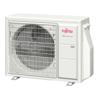
How to connect wiring to the terminal
• When stripping o the coating of a lead wire, always use a special tool such as a wire
stripper. If there is no special tool available, carefully strip the coating with a knife etc.
Earth (Ground) wire
Power cable or
Connection cable
60 mm
75 mm
How to connect wiring to the terminal
Caution when wiring cable
(1) Use crimp-type terminals with insulating sleeves as shown in the gure to con-
nect to the terminal block.
(2) Securely clamp the crimp-type terminals to the wires using an appropriate tool
so that the wires do not come loose.
(3) Use the specied wires, connect them securely, and fasten them so that there is
no stress placed on the terminals.
(4) Use an appropriate screwdriver to tighten the terminal screws. Do not use a
screwdriver that is too small, otherwise, the screw heads may be damaged and
prevent the screws from being properly tightened.
(5) Do not tighten the terminal screws too much, otherwise, the screws may break.
(6) See the table below for the terminal screw tightening torques.
Strip : 10mm
Wire
Terminal blocks
Crimp-type
terminal
Sleeve
Wire
Crimp-type
terminal
Screw with
special washer
Screw with special washer
Crimp-type terminal
Tightening torque [N·m (kgf·cm)]
M4 screw 1.2 to 1.8 (12 to 18)
■
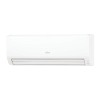
Connection diagrams
B
L
N
1
2
3
B
1
2
3
A
1
2
3
1
2
3
Power cable
Earth (Ground)
POWER
230V
50 Hz · 1ø
Connection cable
Connection cable
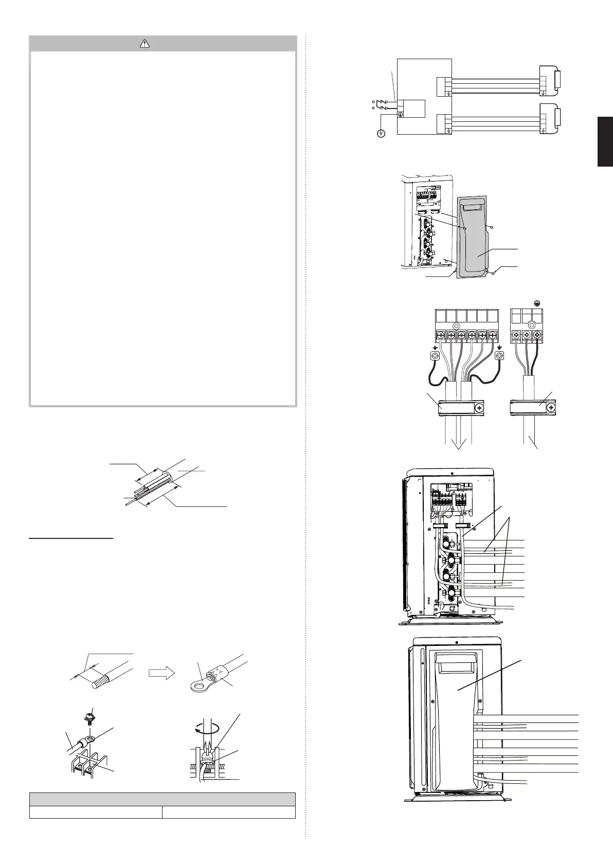
■
Outdoor unit
(1) Switch cover removal
• Remove the xing
screws.
• Lift the switch cover
upward, and then pull it
outward to remove it.
Hook
Switch
cover
Screw
(2) Connect the power
supply cable and the
connection cable to
terminal.
Fasten the power
supply cable and
connection cable with
cable clamp.
POWER
UNIT A UNIT B
Cable
clamp
Cable clamp
Connection cable
Power cable
(3) As illustrated, draw out
the power cable and
the connection cable.
Power cable
Connection cable
(4) Install the switch cover.
Switch cover
9319205281-03_IM.indb 11 04-Dec-20 11:51:22
 Loading...