En-5
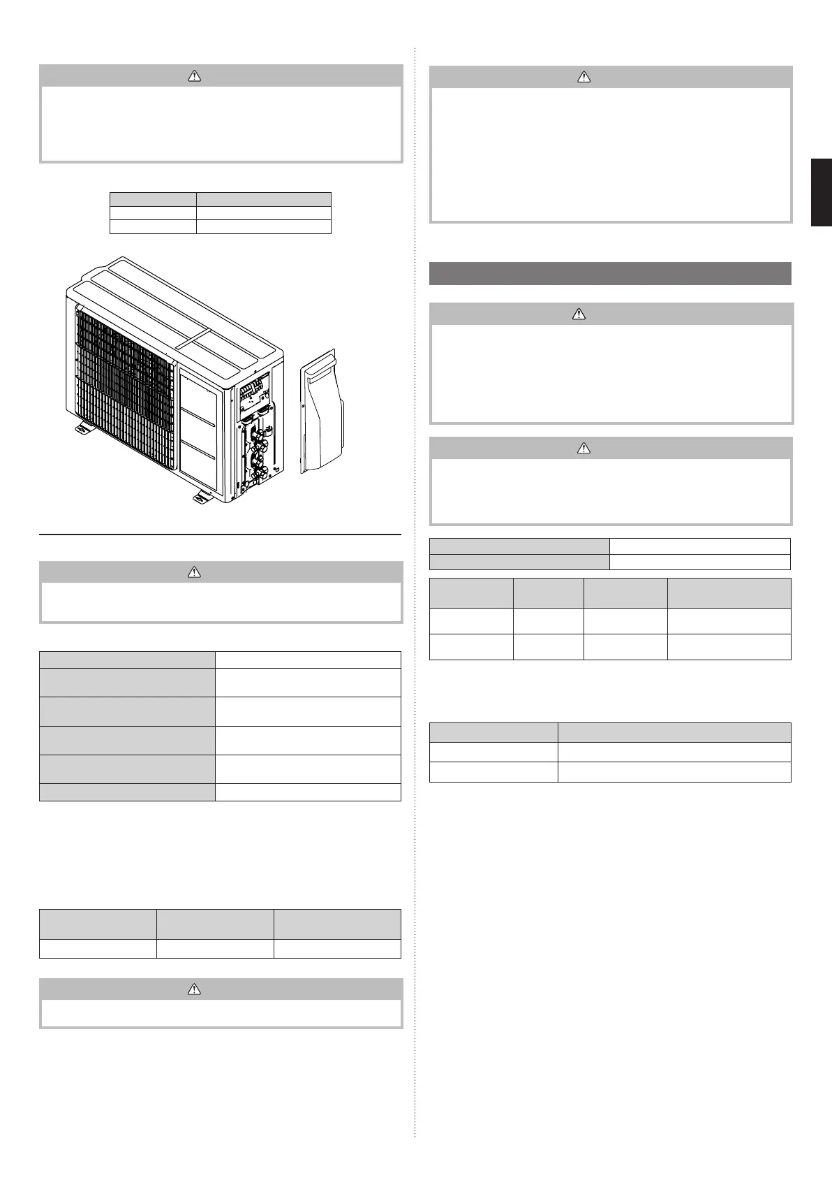
● Connectable indoor unit capacity type
CAUTION
• The total capacity of the indoor units connected must be between 14,000 and
21,000BTU.
• Be sure to check the connecting pattern in technical manual when installed since
connection pattern is specied in it. Operation cannot be guaranteed if connected by
a method not specied in it. It can cause the fault of the product.
• Please connect to both of indoor unit and outdoor unit certainly.
• To install an indoor unit, refer to the installation Manual included with the indoor unit.
Outdoor port Connectable model name
A 7-12
B 7-12
UNIT B ø6.35, ø9.52
UNIT A ø6.35, ø9.52
● Limitation of refrigerant piping length
CAUTION
• The total maximum pipe lengths and height dierence of this product are shown in
the table.
• If the units are further apart than this, correct operation cannot be guaranteed.
Total max. length (a+b) 30 m
*1
Max. length for each indoor unit
(a or b)
20 m
Max. height dierence between out-
door unit and each indoor unit (H1)
15 m
Max. height dierence between
indoor units (H2)
10 m
Min. length for each indoor unit
(a or b)
2.5 m
Total min. length (a+b) 5 m
*1
If the total piping length is longer than 20 m, additional refrigerant charging is neces-
sary. (For more information, refer to “3.8. Additional charging”.)
● Selecting pipe sizes
The diameters of the connection pipes dier according to the capacity of the indoor unit.
Refer to the following table for the proper diameters of the connection pipes between the
indoor and outdoor units.
Capacity of indoor
unit
Gas pipe size
(thickness) [mm]
Liquid pipe size (thick-
ness) [mm]
7 – 14 ø9.52 (0.8) ø6.35 (0.8)
CAUTION
• Operation cannot be guaranteed if the correct combination of pipes, valves, etc., is
not used to connect the indoor and outdoor units.
● Heat insulation around connection pipes requirements
CAUTION
• Install heat insulation around both the gas and liquid pipes. Failure to do so may
cause water leaks.
• Use heat insulation with heat resistance above 120 °C. (Reverse cycle model only)
• In addition, if the humidity level at the installation location of the refrigerant piping is
expected to exceed 70%, install heat insulation around the refrigerant piping. If the
expected humidity level is 70-80%, use heat insulation that is 15 mm or thicker and if
the expected humidity exceeds 80%, use heat insulation that is 20 mm or thicker.
• If heat insulation is used that is not as thick as specied, condensation may form on
the surface of the insulation.
• In addition, use heat insulation with heat conductivity of 0.045 W/(m·K) or less
Connect the connection pipes according to “3.5. Pipe installation” in this installation
Manual.
2.4. Electrical requirements
WARNING
• Always use a special branch circuit and install a special receptacle to supply power to
the air conditioner.
• Use a special branch circuit breaker and receptacle matched to the capacity of the air
conditioner. (Install in accordance with standard.)
• Perform wiring work in accordance with standards so that the air conditioner can be
operated safely and positively.
• Install a leakage special branch circuit breaker in accordance with the related laws
and regulations and electric company standards.
CAUTION
• When the voltage is low and the air conditioner is dicult to start, contact the power
company the voltage raised.
• Be sure to install a breaker of the specied capacity.
• Regulation of cables and breaker diers from each locality, refer in accordance with
local rules.
Voltage rating 1 Φ 230 V (50 Hz)
Operating range 198 to 264 V
Cable
Cable size
(mm
2
)
*1
Type Remarks
Power supply cable 1.5 Type 60245 IEC 57
2 cable + Earth (Ground),
1 Ø 230V
Connection cable 1.5 Type 60245 IEC 57
3 cable + Earth (Ground),
1 Ø 230V
*1
Selected sample: Select the correct cable type and size according to the country or
region’s regulations.
Max. wire length: Set a length so that the voltage drop is less than 2%. Increase the
wire diameter when the wire length is long.
Breaker Specication
*2
Circuit breaker (over current) Current : 15 (A)
Earth leakage breaker Leakage current : 30mA 0.1sec or less
*3
*2
Select the appropriate breaker of the described specication according to the national
or regional standards.
*3
Select the breaker that enough load current can pass through it.
• Before starting work check that power is not being supplied to all poles of the indoor unit
and outdoor unit.
• Install all electrical works in accordance to standard.
• Install the disconnect device with a contact gap of at least 3mm in all poles nearby the
units. (Both indoor unit and outdoor unit)
• Wiring size must comply with the applicable local and national code.
9319205281-03_IM.indb 5 04-Dec-20 11:51:17
 Loading...