EasyManua.ls Logo

Fujitsu AOYS12LDC - User Manual

Fujitsu AOYS12LDC
108 pages
Print Icon
To Next Page IconTo Next Page
Loading...
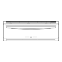
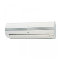
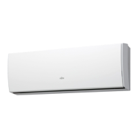
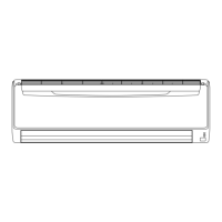
SPLIT TYPE
ROOM AIR CONDITIONER
WALL MOUNTED
type
Models Indoor unit Outdoor unit
ASYA07LCC
ASYA09LCC
ASYA12LCC
ASYA14LCC
ASYA18LCC
ASYB09LDC
ASYB12LDC
AOYR07LCC
AOYR09LCC
AOYR12LCC
AOYR14LCC
AOYR18LCC
AOYS09LDC
AOYS12LDC
INVERTER
SERVICE
INSTRUCTION
R410A

Other manuals for Fujitsu AOYS12LDC

Questions and Answers

  • L
    Lauren GrahamSep 2, 2025
    Why Fujitsu AOYS12LDC shows serial reverse transfer error at starting up operation?
    • B
      batesstephanieSep 2, 2025
      If your Fujitsu Air Conditioner displays a serial reverse transfer error at startup, it means the indoor unit isn't receiving a signal for 10 seconds after the power relay turns on. Check the indoor/outdoor cable connection. If the wiring is normal, measure the voltage of the outdoor unit terminals and diagnose the defective location.
  • C
    charlesrodriguezAug 31, 2025
    What does main relay error mean on Fujitsu AOYS12LDC Air Conditioner?
    • J
      Jennifer WoodsAug 31, 2025
      If your Fujitsu Air Conditioner displays a main relay error, it means that after 2 minutes 20 seconds of stopping operation, the signal from the outdoor unit is received even though the main relay is OFF. The main relay might be defective or the Controller PCB might be defective.
  • A
    Andrea FlemingAug 29, 2025
    What causes a room temperature thermistor defective in Fujitsu AOYS12LDC?
    • G
      Grant DavisAug 30, 2025
      If your Fujitsu Air Conditioner shows a room temperature thermistor defect, it means the thermistor detected an abnormal temperature when the power was turned on. Check the thermistor resistance value. The controller PCB might be defective.
  • C
    chadchangAug 28, 2025
    What to do if my Fujitsu Air Conditioner has indoor fan speed error?
    • A
      April BrandtAug 28, 2025
      If your Fujitsu Air Conditioner displays an indoor fan speed error, it means the indoor fan speed is 1/3 of the target frequency after 56 seconds from starting or changing the fan mode. Here’s what to check: * Check the fan motor connector for looseness or defective contact. * The fan motor might be defective. * The controller PCB might be defective.
  • R
    Rachael ThompsonAug 27, 2025
    What to do if my Fujitsu Air Conditioner has indoor fan lock error?
    • S
      Shannon SmithAug 27, 2025
      If your Fujitsu Air Conditioner displays an indoor fan lock error, it means the indoor fan speed is 0 rpm after 56 seconds from starting or changing the fan mode. Here’s what to check: * Check the fan motor connector for looseness or defective contact. * The fan motor might be defective. * The controller PCB might be defective.
  • D
    Dawn MortonAug 25, 2025
    What causes IPM protection in my Fujitsu AOYS12LDC Air Conditioner?
    • J
      Jason OrtizAug 25, 2025
      If your Fujitsu Air Conditioner is showing IPM protection, it indicates that an abnormal current value has been detected. Here's what you should check: * Ensure that heat radiation is not blocked at the inlet or outlet. * Verify that the outdoor fan is functioning correctly and rotating. * The controller PCB might be defective.
  • E
    Erin MitchellAug 22, 2025
    What to do if my Fujitsu Air Conditioner shows excessive high pressure protection on cooling?
    • K
      Kaitlyn MartinezAug 22, 2025
      If your Fujitsu Air Conditioner is showing an excessive high pressure protection error during cooling, check the following: * Ensure that heat radiation is not blocked at the inlet or outlet. * Verify that the outdoor fan is functioning correctly and rotating. * Check for any issues with the refrigeration cycle.

Summary

1. SPECIFICATION

6. REFRIGERANT CAUTION -R410 A-

7. TROUBLE SHOOTING

Does not operate at all (Operation Lamp and Timer Lamp do not light up)

Troubleshooting steps for units that do not operate at all.

SELF-DIAGNOSIS FUNCTION

Explains the self-diagnosis function and memory reading.

Serial Signal Receiving Error

Troubleshooting steps for serial signal receiving errors between units.

IPM Protection

Checks and causes for IPM protection errors in the outdoor unit.

Trouble Shooting of Refrigerant Cycle

Diagnosis table and methods for refrigerant cycle issues.

8. APPENDING DATA

JP (Jumper) Setting

Explains indoor and outdoor unit jumper settings for custom codes and auto restart.

Outdoor Unit Low Pressure Value and Outdoor Total Electric Current Curve (Cooling)

Presents cooling performance curves for low pressure and current.

Outdoor Unit High Pressure Value and Outdoor Total Electric Current Curve (Heating)

Presents heating performance curves for high pressure and current.

Thermistor resistance values

Lists resistance values for various thermistors at different temperatures.

Room temperature thermistor

Resistance values for room temperature thermistors.

Indoor heat exchanger thermistor

Resistance values for indoor heat exchanger thermistors.

Discharge thermistor

Resistance values for discharge thermistors.

Outdoor heat exchanger thermistor

Resistance values for outdoor heat exchanger thermistors.

Outdoor temperature thermistor

Resistance values for outdoor temperature thermistors.

ASYA09 LCC Capacity;Input data (1;2)

Cooling and heating capacity/input graphs for ASYA09LCC.

ASYA12 LCC Capacity;Input data (1;2)

Cooling and heating capacity/input graphs for ASYA12LCC.

ASYA18 LCC Capacity;Input data (1;2)

Cooling and heating capacity/input graphs for ASYA18LCC.

ASYB09 LDC Capacity;Input data (1;2)

Cooling and heating capacity/input graphs for ASYB09LDC.

ASYB12 LDC Capacity;Input data (1;2)

Cooling and heating capacity/input graphs for ASYB12LDC.

9. REPLACEMENT PARTS

PROCESS Wiring lead wire

Instructions for wiring lead wires for the inverter assembly.

Process Connection of leads to inverter assy

Shows how to connect leads to the inverter assembly.

Process Shaping of leads to inverter assy

Illustrates shaping of leads for the inverter assembly.

PROCESS ATTACHMENT OF INVERTER ASSY

Details the process of attaching the inverter assembly.

PROCESS The leads are connected with INVERTER ASSY

Shows how leads are connected to the inverter assembly with labels.

PROCESS Fixing of Thermistor lead and motor lead.

Illustrates fixing of thermistor and motor leads.

SPLIT TYPE ROOM AIR CONDITIONER INSTALLATION MANUAL

STANDARD ACCESSORIES

Lists standard installation accessories supplied with the product.

ELECTRICAL REQUIREMENT

Specifies requirements for the air conditioner's power supply.

SELECTING THE MOUNTING POSITION

Provides guidelines for choosing indoor and outdoor unit mounting locations.

1. INDOOR UNIT

Guidelines for selecting the indoor unit mounting position.

2. OUTDOOR UNIT

Guidelines for selecting the outdoor unit mounting position.

INSTALLATION DIAGRAM OF INDOOR AND OUTDOOR UNITS

Illustrates the installation layout of indoor and outdoor units.

FRONT PANEL REMOVAL AND INSTALLATION

Instructions for removing and installing the front panel and intake grille.

AIR CLEANING UNIT REMOVAL

Steps to remove the air cleaning unit from the indoor unit.

AIR CLEANING UNIT INSTALLATION

Steps to install the air cleaning unit into the indoor unit.

CUSTOMER GUIDANCE

Advice on explaining operation and maintenance to the customer.

PUMP DOWN OPERATION (FORCED COOLING OPERATION)

Procedure for recovering refrigerant before unit relocation or disposal.

FINISHING

Instructions for insulating pipes and sealing gaps.

INDOOR UNIT

Specific installation steps for the indoor unit.

CUTTING THE HOLE IN THE WALL FOR THE CONNECTING PIPING

Details on cutting the wall hole for piping.

INSTALLING THE WALL HOOK BRACKET

Guidelines for securely installing the wall hook bracket.

FORMING THE DRAIN HOSE AND PIPE

Instructions for forming and routing the drain hose and piping.

INDOOR UNIT WIRING

Steps for connecting the indoor unit wiring.

OUTDOOR UNIT

Specific installation steps for the outdoor unit.

OUTDOOR UNIT INSTALLATION

General installation guidelines for the outdoor unit.

AIR PURGE

Procedure for purging air from the refrigerant circuit.

OUTDOOR UNIT WIRING

Steps for connecting the outdoor unit wiring.

CONNECTION

General connection steps for piping.

FLARING

Instructions for flaring refrigerant pipes.

CONNECTING THE PIPING

Steps for connecting the refrigerant piping.

TEST RUNNING

Procedures for performing test operation after installation.

Fujitsu AOYS12LDC Specifications

General IconGeneral
TypeSplit System
Cooling Capacity3.4 kW
Heating Capacity4.0 kW
RefrigerantR410A
Noise Level (Outdoor)50 dB(A)
Power Supply220-240V, 50Hz
Indoor Unit Weight9 kg

Related product manuals