1
2
3
L
N
EMI FILTER
TRCB-25-15-12
3 T
EMI FILTER
GRFC-13
2 T
TERMINAL EMI FILTER
GRFC-8
1 T
EMI FILTER
GRFC-7
3 T
EMI FILTER
ZCAT2132-1130
1 T
5V-1
5V-1 5V-1
380V
15V-1
13V-3
13V-4
5V-1
5V-3
13V-3
13V-4
5V-3
13V-3
F101
10A
AC250V
F102
10A
AC250V
F103
3.15A
AC250V
1
2
3
4
5
6
7
8
9
10
11
12
1
2
3
4
1
2
3
4
1
2
3
4
5
1
2
3
4
5
1
2
3
4
1
2
1
2
1
2
1
2
1
2
3
4
5
6
7
8
9
10
11
12
1
2
3
4
1
2
3
1
2
3
4
1
2
3
1
2
3
1
2
3
1
2
3
1
2
3
4
5
1
3
5
UL1015
AWG12
GREEN
UL1015
AWG20
GREEN
UL1015
AWG20
GREEN
UL1015 AWG20 WHITE
UL1015 AWG20 BLACK
UL1015 AWG20 RED
UL1015 AWG12 WHITE
UL1015 AWG12 BLACK
BLACK
BLACK
ORANGE
YELLOW
WHITE
BLUE
RED
RED
WHITE
BLACK
BLACK
BLACK
BLACK
BLACK
BLACK
BLACK
BLACK
BLACK
BLACK
BLACK
MARKING COLOR RED
MARKING COLOR BROWN
MARKING COLOR GRAY
GND_C
GND_A
GND_C
GND_D
GND_D
GND_C
GND_A
GND_A
GND_A
UL3271 AWG12 RED
UL1430 AWG22 x 5
UL3271 AWG12 WHITE
UL3271 AWG12 BLACK
1
4
5
6
7
1
4
5
6
7
RED
BLACK
WHITE
YELLOW
BROWN
RED
BLACK
WHITE
YELLOW
BROWN
UL1430 AWG24 x 2 UL1430 AWG22 x 2
WHITE
WHITE
WHITE
WHITE
1
2
3
1
2
3
1
2
BLACK
BLACK
UL1430 AWG24 WHITE
UL1430 AWG24 WHITE
UL1430 AWG24 WHITE
UL1430 AWG24 WHITE
UL1430 AWG24 WHITE
UL1430 AWG24 WHITE
UL1430 AWG24 WHITE
UL1430 AWG24 WHITE
UL1430 AWG24 WHITE
UL1430 AWG24 WHITE
UL1015 AWG14 WHITE
UL1015 AWG14 BLACK
UL3271
AWG14
RED
W200
L-IN
W201
N-IN
W202
RELAY-OUT
W203
DB-IN
P351
B04B-XNISK-A-1
WHITE
P600
B12B-PASK-1
WHITE
P662
B05B-PASK-1
WHITE
P663
B04B-PASK-1
WHITE
POWER SUPPLY ( DC13V-4 )
MAIN - INV. COM.
FLASH
EX. IN 1
EX. IN 2
EX. OUT 1
EX. OUT 2
P580
B02B-XAYK-1-A
YELLOW
PA580
B02B-XAMK-1-A
GREEN
P590
B02B-XAKK-1-A
BLACK
P590
B02B-XAEK-1-A
BLUE
P661
B04B-PASK-1
WHITE
P710
B12B-PASK-1
WHITE
P660
B05B-PASK-1
WHITE
P350
B04B-XNISK-A-1
WHITE
P108
B3 ( 8.0 ) B-PSILE-1
BLUE
P102
L-IN
P103
N-IN
P109
E
P60
B2P3-VH-B
WHITE
P30
B05B-PLISK-1
WHITE
P20
B03B=XASK-1-A
WHITE
P10
B03B=PASK-1
WHITE
P1
B03B=PLIEK-1
BLUE
P15
B04B=PLIRK-1
RED
P5
B03B=PLISK-1
WHITE
P106
L-OUT
P107
N-OUT
P700
B03B-XAKK-1-A
BLACK
P770
B03B-XNISK-A-1
WHITE
P650
B5 ( 7-2.3 ) B-XASK-1-A
WHITE
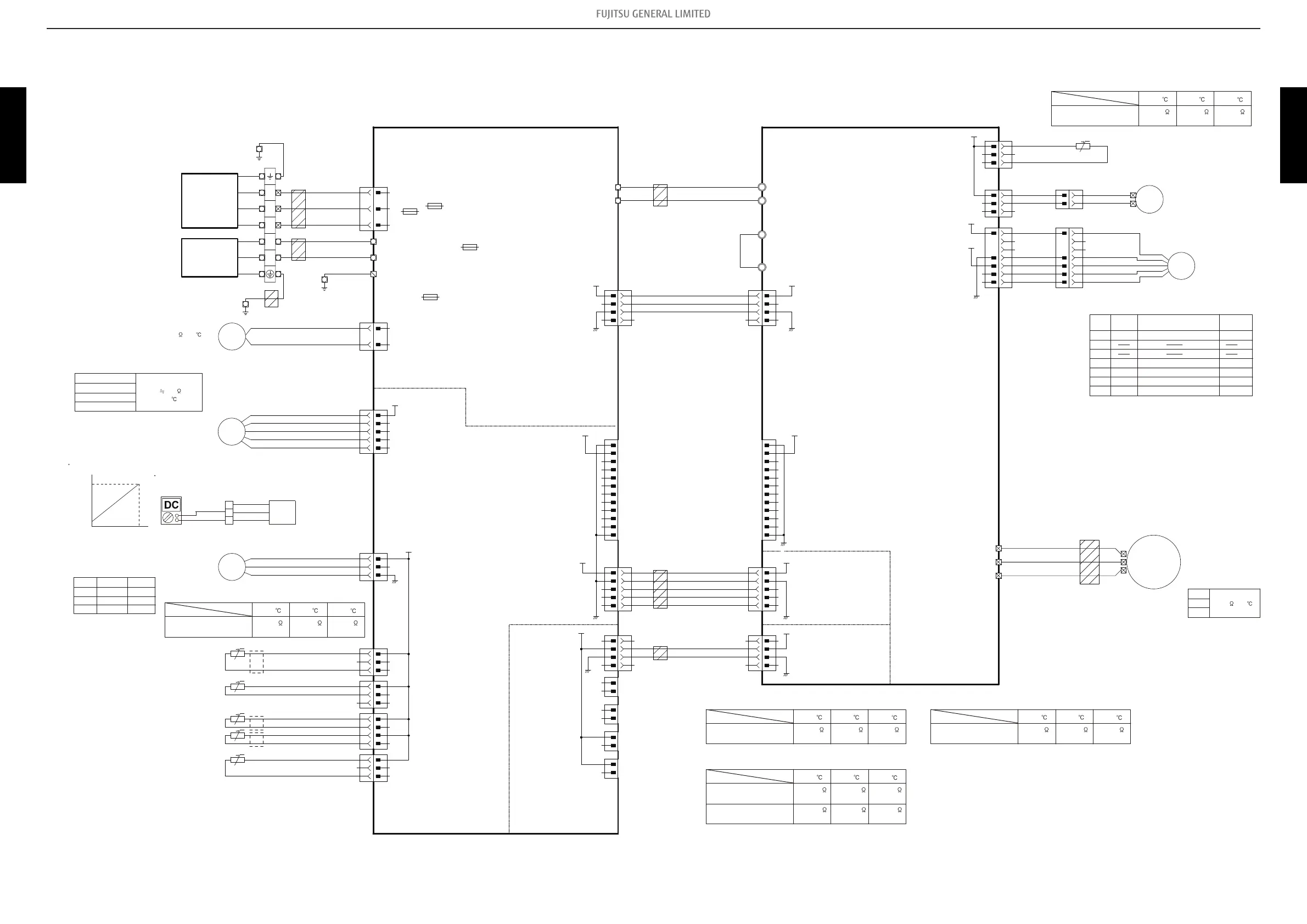
P400 U
P401 V
P402 W
COMPRESSOR
DC FAN MOTOR 1
HIGH PRESSURE SWITCH
THERMISTOR ( HEATSINK TEMP. )
EXPANSION VALVE COIL 1
HIGH PRESSURE SENSOR
THERMISTOR ( COMP. TEMP. )
THERMISTOR ( PIPE-MID. TEMP. )
THERMISTOR ( PIPE-OUT TEMP. )
THERMISTOR ( DISCHARGE TEMP. )
THERMISTOR ( OUTDOOR TEMP. )
4WV
EEV1
PRES.
SENSOR
HI
FM
HP
SW1
COMP.
U-V
V-W
U-W
Compressor
Winding Resistance
0.766
(20 )
1
3
4
5
6
Pin No.
Terminal
code
Vm
GND
Vcc
Vsp
FG
Function of terminal
Revolution pulse output
Speed control voltage input
Control power voltage input
GND
Motor power voltage input
Lead wire
color
Red
Black
White
Yellow
Brown
2
7
P650 DC Fan Motor
CT
CT
FLASH / EEPROM
EMI FILTER
GRFC-13
2 T
EMI FILTER
GRFC-7
1 T
4-WAY VALVE COIL
DC Resistance 1970
(20 )
1(Red) - 3(Blue)
1(Red) - 4(Orange)
1(Red) - 5(Yellow)
1(Red) - 6(White)
P30 Expansion Valve Coil
46.0
(20 )
Recommended Drive Condition
Unipolar Drive, 1-2 Phase Excitation.
Coil resistance
Pin No.
Wiring and coloring
1
3
2
Signal Color
Vcc
Vout
GND
Red
White
Black
With the connector connected to the Main PCB,
measure the voltage between P20 : 2 - 3 of the Main PCB
P20
P Discharge pressure sensor
1
RED
WHITE
BLACK
+
-
3
2
Characteristics of pressure sensor
4.5
5.0
0.5
0
Output [DCV]
Pressure [MPa]
S
P700 Thermistor Characteristics.
0 20
30
Thermistor
Thermistor ( Heatsink temp. )
0.33 k
4.10 V
Temperature
0.12 k
4.62 V
0.08 k
4.75 V
P10 Thermistor Characteristics.
0 20
30
Thermistor
Thermistor ( Compressor temp. )
168.61 k
0.36 V
Temperature
62.55 k
0.86 V
40.01 k
1.23 V
P1 Thermistor Characteristics.
0 20
30
Thermistor
Thermistor ( Pipe-mid. temp. )
16.05 k
1.14 V
Temperature
5.98 k
2.21 V
3.84 k
2.77 V
Thermistor ( Discharge temp. )
P15 Thermistor Characteristics.
0 20
30
Thermistor
Thermistor ( Pipe temp. )
Temperature
16.05 k
1.14 V
5.98 k
2.21 V
3.84 k
2.77 V
168.61 k
0.36 V
62.55 k
0.86 V
40.01 k
1.23 V
P5 Thermistor Characteristics.
0 20
30
Thermistor
Thermistor ( Outdoor temp. )
35.21 k
2.61 V
Temperature
12.64 k
3.80 V
7.97 k
4.14 V
TRANSISTOR PCB
( INVERTER PCB )
K17PH-1902SUE-TR1-SV
MAIN PCB
36 model : G36KBTB(Y)-A02-SV
45 model : G45KBTB(Y)-A02-SV
F100
30or35A
AC250V
INDOOR UNIT
POWER SOURCE
AC230V
50Hz
INVERTER ASSEMBLY
36 model : EZ-0190DHUE
45 model : EZ-0193KHUE
8-6. Models: AOYG30KBTB, AOYG36KBTB, and AOYG45KBTB - (02-43) - 8. PC board diagrams
 Loading...