En-10
8. HOW TO OPERATE DISPLAY UNIT
8.1. Various setting methods
WARNING
Never touch electrical components such as the terminal blocks or reactor except the
switch on the display board. It may cause a serious accident such as electric shock.
CAUTION
Once refrigerant charging is completed, be sure to open the valve prior to performing
the local settings. Otherwise, the compressor may fail.
Discharge any static electricity from your body before touching the push switches. Never
touch any terminal or pattern of any parts on the control board.
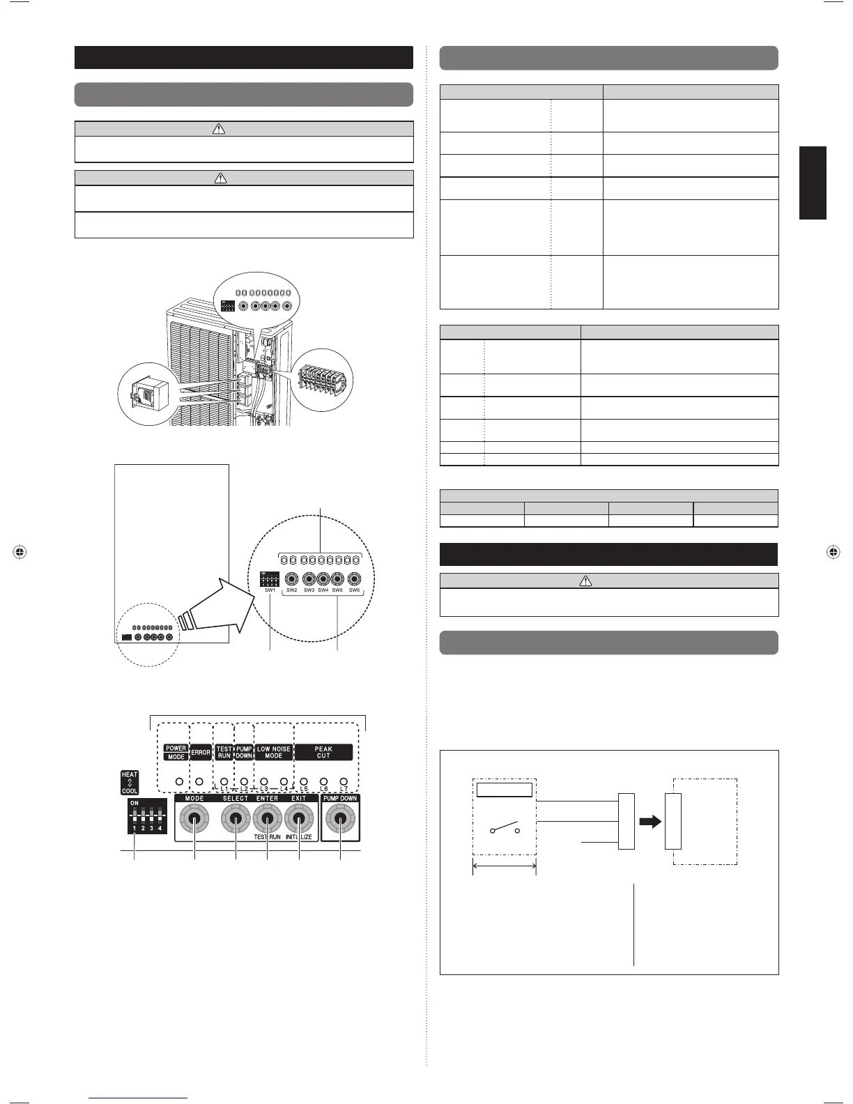
The positions of the switches on the outdoor unit control board are shown in the fi gure •
below.
Terminal blocks
Reactors
Various settings can be adjusted by changing DIP switches and push switches on the •
board of the outdoor unit.
DIP switch
Push
switches
LED display
The printed characters for the LED display are shown below.•
SW1 SW2
SW3 SW4 SW5
SW6
(1)
(2) (3)
(4)
(5)
(6)
LED display part
8.2. Description of display
Display lamp
Function or operation method
(1) POWER/MODE Green
Lights on while power on Local setting in
outdoor unit or error code is displayed with
blink.
(2) ERROR Red
Blinks during abnormal air-conditioner
operation.
(3) TEST RUN
(L1)
Orange Lights on during test operation.
(4) PUMP DOWN
(L2)
Orange Lights on during pump down operation.
(5) LOW NOISE MODE
(L3, L4)
Orange
Lights on during “Low noise” function when
local setting is activated.
(Lighting pattern of L3 and L4 indicates
low noise level)
B
Refer to “9. LOCAL
SETTING”.
(6) PEAK CUT
(L5, L6, L7)
Orange
Lights on during “Peak cut” function when
local setting is activated.
(Lighting pattern of L5, L6 and L7 indicates
peak cut level)
B
Refer to “9. LOCAL
SETTING”.
Switch
Function or operation method
SW1 DIP switch
For selecting cooling or heating during test
operation.
Positions 2 to 4 of DIP switch are not used.
SW2 Push switch
To switch between “Local setting” and “Error code
display”.
SW3 Push switch
To switch between the individual “Local settings”
and the “Error code displays”.
SW4 Push switch
To fi x the individual “Local settings”, “Test run” and
the “Error code displays”.
SW5 Push switch EXIT
SW6 Push switch To start the pump down operation.
DIP switches 1 to 4 at shipment from the factory are set as follows.•
DIP switch
1234
COOL OFF OFF OFF
s d
9. LOCAL SETTING
CAUTION
Discharge the static electricity from your body before setting up the switches.
Never touch the terminals or the patterns on the parts that are mounted on the board.
9.1. Low noise mode (Local work)
Outdoor unit may be operated with lower noise than normal operation when following
below local work.
Low noise operation is available by installation of an additional commercially available •
timer or contact input from the ON-OFF switch to the CN19 connector (an external
contact input sold separately) on the control board of the outdoor unit.
* Performance may be defi cient depending on outdoor temperature or conditions etc.
< Example of circuit diagram >
Outdoor unit control
board
Remote control
panel
Adapter for
external input
CN19
Power supply
Red
White
Black
1
2
3
1
2
3
SW1
Local purchase
(1) Make a circuit of the above fi gure with
an “Adapter for external input” sold
separately.
(2) Low noise operation can be set up with
the operation of external display portion.
SW1...ON
Level 1
(Shipment condition)
Level 2
SW1...OFF
Normal operation
9379069403_IM.indb 109379069403_IM.indb 10 1/29/2013 4:44:20 PM1/29/2013 4:44:20 PM
 Loading...