En-6
5.3.1. Flaring
Use special pipe cutter and fl are tool exclusive for R410A.
(1) Cut the connection pipe to the necessary length with a pipe cutter.
(2) Hold the pipe downward so that the cuttings will not enter the pipe and remove any
burrs.
(3) Insert the fl are nut (always use the fl are nut attached to the indoor and outdoor
units respectively) onto the pipe and perform the fl are processing with a fl are tool.
Leakage of refrigerant may result if other fl are nuts are used.
(4) Protect the pipes by pinching them or with tape to prevent dust, dirt, or water from
entering the pipes.
Check if [L] is fl ared uniformly
and is not cracked or scratched.
B
L
Pipe
A
Die
Pipe outside diameter
[mm (in.)]
Dimension A [mm]
Flare tool for R410A, clutch type
6.35 (1/4)
0 to 0.5
9.52 (3/8)
12.70 (1/2)
15.88 (5/8)
19.05 (3/4)
Pipe outside diameter
[mm (in.)]
Dimension B
0
[mm]
- 0.4
6.35 (1/4) 9.1
9.52 (3/8) 13.2
12.70 (1/2) 16.6
15.88 (5/8) 19.7
19.05 (3/4) 24.0
When using conventional fl are tools to fl are R410A pipes, the dimension A should be
approximately 0.5 mm more than indicated in the table (for fl aring with R410A fl are tools)
to achieve the specifi ed fl aring. Use a thickness gauge to measure the dimension A.
Pipe outside
diameter [mm (in.)]
Width across fl ats
of Flare nut [mm]
6.35 (1/4) 17
9.52 (3/8) 22
12.70 (1/2) 26
15.88 (5/8) 29
19.05 (3/4) 36
Width across fl ats
5.3.2. Bending pipes
CAUTION
To prevent breaking of the pipe, avoid sharp bends. Bend the pipe with a radius of
curvature of 100 mm to 150 mm.
If the pipe is bent repeatedly at the same place, it will break.
If pipes are shaped by hand, be careful not to collapse them.•
Do not bend the pipes at an angle of more than 90°.•
When pipes are repeatedly bent or stretched, the material will harden, making it diffi cult •
to bend or stretch them any more.
Do not bend or stretch the pipes more than three times.•
5.3.3. Pipe connection
CAUTION
Be sure to install the pipe against the port on the indoor unit and the outdoor unit
correctly. If the centering is improper, the fl are nut cannot be tightened smoothly. If the
fl are nut is forced to turn, the threads will be damaged.
Do not remove the fl are nut from the outdoor unit pipe until immediately before
connecting the connection pipe.
After installing the piping, make sure that the connection pipes do not touch the
compressor or outer panel. If the pipes touch the compressor or outer panel, they will
vibrate and produce noise.
(1) Detach the caps and plugs from the pipes.
(2) Center the pipe against the port on the outdoor unit, and then turn the fl are nut by
hand.
(3) Tighten the fl are nut of the connection pipe at the outdoor unit valve connector.
3-way valve (Liquid)
3-way valve (Gas)
Flare nut
Connection pipe
(Liquid)
Flare nut
Connection pipe
(Gas)
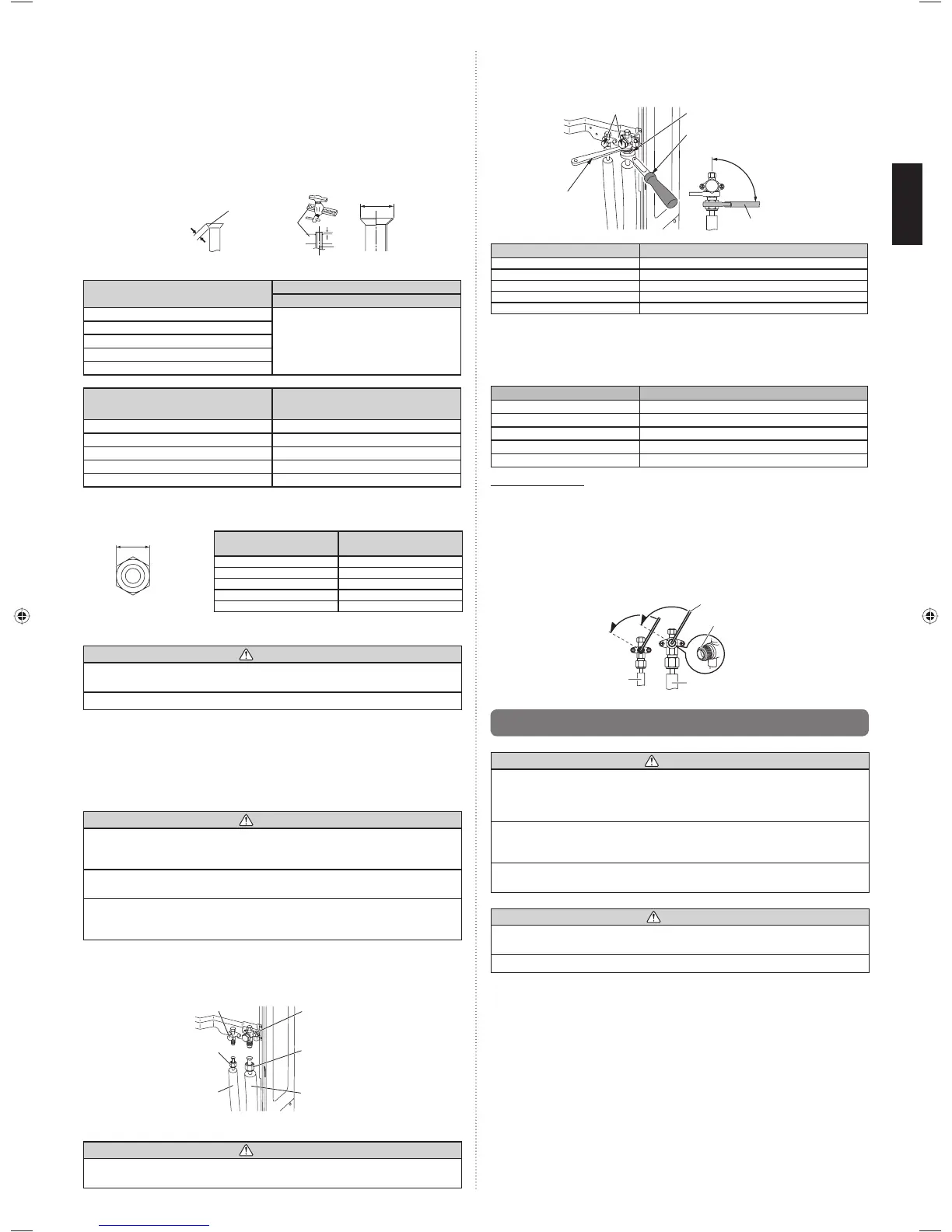
(4) After tightening the fl are nut by hand, use a torque wrench to fully tighten it.
CAUTION
Hold the torque wrench at its grip, keeping it in a right angle with the pipe, in order to
tighten the fl are nut correctly.
Outer panel may be distorted if fastened only with a wrench. Be sure to fi x the •
elementary part with a spanner and fasten with a wrench (refer to below diagram).
Do not apply force to the blank cap of the valve or hang a wrench, etc., on the cap. It •
may cause leakage of refrigerant.
Blank cap
Flare nut
Torque wrench
Holding
wrench
Torque wrench
90°
Flare nut
[mm (in.)]
Tightening torque
[N·m (kgf·cm)]
6.35 (1/4) dia. 16 to 18 (160 to 180)
9.52 (3/8) dia. 32 to 42 (320 to 420)
12.70 (1/2) dia. 49 to 61 (490 to 610)
15.88 (5/8) dia. 63 to 75 (630 to 750)
19.05 (3/4) dia. 90 to 110 (900 to 1100)
5.3.4. Handling precautions for the valves
Mounted part of Blank cap is sealed for protection.•
Fasten blank cap tightly after opening valves.•
Table A
Blank cap
[mm (in.)]
Tightening torque
[N·m (kgf·cm)]
6.35 (1/4) 20 to 25 (200 to 250)
9.52 (3/8) 20 to 25 (200 to 250)
12.70 (1/2) 25 to 30 (250 to 300)
15.88 (5/8) 30 to 35 (300 to 350)
19.05 (3/4) 35 to 40 (350 to 400)
Operating the valves
Use a hexagon wrench (size 4 mm).•
Opening (1) Insert the hexagon wrench into the valve shaft, and turn it •
counterclockwise.
(2) Stop turning when the valve shaft can no longer be turned.
(Open position)
Closing (1) Insert the hexagon wrench into the valve shaft, and turn it clockwise.•
(2) Stop turning when the valve shaft can no longer be turned.
(Closed position)
Opening direction
Hexagon wrench
Seal (blank cap
installation portion)
Liquid pipe
Gas pipe
Opening direction
5.4. Sealing test
WARNING
Before operating the compressor, install the pipes and securely connect them.
Otherwise, if the pipes are not installed and if the valves are open when the compressor
operates, air could enter the refrigeration cycle. If this happens, the pressure in the
refrigeration cycle will become abnormally high and cause damage or injury.
After the installation, make sure there is no refrigerant leakage. If the refrigerant leaks
into the room and becomes exposed to a source of fi re such as a fan heater, stove, or
burner, it produces a toxic gas.
Do not subject the pipes to strong shocks during the sealing test. It can rupture the
pipes and cause serious injury.
CAUTION
Do not block the walls and the ceiling until the sealing test and the charging of the
refrigerant gas have been completed.
For maintenance purposes, do not bury the piping of the outdoor unit.
After connecting the pipes, perform a sealing test.•
Make sure that the 3-way valves are closed before performing a sealing test.•
Pressurize nitrogen gas to 4.15 MPa to perform the sealing test.•
Add nitrogen gas to both the liquid pipes and the gas pipes.•
Check all fl are connections and welds. Then, check that the pressure has not •
decreased.
Compare the pressures after pressurizing and letting it stand for 24 hours, and check •
that the pressure has not decreased.
* When the outdoor air temperature changes 5 °C, the test pressure changes
0.05 MPa. If the pressure has dropped, the pipe joints may be leaking.
If a leak is found, immediately repair it and perform the sealing test again.•
After completing the sealing test, release the nitrogen gas from both valves.•
Release the nitrogen gas slowly.•
9379069403_IM.indb 69379069403_IM.indb 6 1/29/2013 4:44:19 PM1/29/2013 4:44:19 PM
 Loading...