En-11
9.2. Peak cut mode (Local work)
Effi cient operation while reducing power supply and power consumption with below local
work.
Peak cut function can be effective with contact installation of an additional ON-OFF •
switch to the CN19 connector on the outdoor control board.
< Example of circuit diagram >
Outdoor unit
control board
Adapter for
external input
CN19
Power supply
Red
White
Black
1
2
3
1
2
3
SW2
Remote control
panel
Local purchase
(1) Make a circuit like above fi gure using an
“Adapter external input” sold separately.
(2) Set a restriction for below power
consumption (compared with the rated
consumption). Refer to “8. HOW TO
OPERATE DISPLAY UNIT” for settings.
SW2...ON
Level 1 : 0% (Stop)
Level 2 : 50%
Level 3 : 75%
Level 4 : 100%
(Shipment condition)
SW2...OFF
Normal operation
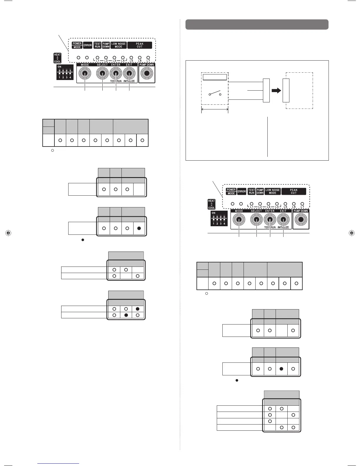
9.2.1. Setting for peak cut
SW2
SW3 SW4 SW5
LED display part
(1) Switch to “Local setting mode” by pressing MODE switch (SW2) for 3 seconds or
more.
(2) Confi rm POWER/MODE LED blinks 9 times, and press ENTER switch (SW4).
POWER
MODE
ERROR
TEST
RUN
(L1) (L2) (L3) (L4) (L5) (L6) (L7)
PUMP
DOWN
LOW NOISE PEAK CUT
Blinks
(9 times)
Sign “ ” : Lights off
(3) Press SELECT switch (SW3), and adjust LED display as shown below. (Current
setting is displayed)
TEST
RUN
(L1) (L2) (L3) (L4)
PUMP
DOWN
LOW NOISE
Blink
PEAK CUT
MODE
(4) Press ENTER switch (SW4).
TEST
RUN
(L1) (L2) (L3) (L4)
PUMP
DOWN
LOW NOISE
PEAK CUT
MODE
Sign “ ” : Lights on
(5) Press SELECT switch (SW3), and adjust LED display as shown in below fi gure.
PEAK CUT
(L5) (L6) (L7)
Blink
Blink
Blink Blink
Blink
0% of rated input ratio
50% of rated input ratio
75% of rated input ratio
100% of rated input ratio
9.1.1. Setting for low noise
SW2
SW3 SW4 SW5
LED display part
(1) Switch to “Local setting mode” by pressing MODE switch (SW2) for 3 seconds or
more.
(2) Confi rm POWER/MODE LED blinks 9 times, and press ENTER switch (SW4).
POWER
MODE
ERROR
TEST
RUN
(L1) (L2) (L3) (L4) (L5) (L6) (L7)
PUMP
DOWN
LOW NOISE PEAK CUT
Blinks
(9 times)
Sign “ ” : Lights off
(3) Press SELECT switch (SW3), and adjust LED display as shown below. (Current
setting is displayed)
TEST
RUN
(L1) (L2) (L3) (L4)
PUMP
DOWN
LOW NOISE
LOW NOISE
MODE
Blink
(4) Press ENTER switch (SW4).
LOW NOISE
MODE
TEST
RUN
(L1) (L2) (L3) (L4)
PUMP
DOWN
LOW NOISE
Sign “ ” : Lights on
(5) Press SELECT switch (SW3), and adjust LED display as shown in below fi gure.
PEAK CUT
(L5) (L6) (L7)
Blink
Blink
Level 1
Level 2
(6) Press ENTER switch (SW4) and fi x it.
PEAK CUT
(L5) (L6) (L7)
Level 1
Level 2
(7) Return to “Operating status display (Normal operation)” by pressing EXIT switch
(SW5).
In case of missing how many times SELECT and ENTER switch are pressed, restart
from the beginning of operation procedure after returning to “Operation status display
(normal operation)” by pressing the EXIT switch once.
9379069403_IM.indb 119379069403_IM.indb 11 1/29/2013 4:44:20 PM1/29/2013 4:44:20 PM
 Loading...