En-6
Double-twin type
Capacity [Btu/h class] 72,000 90,000
Indoor unit capacity
[Btu/h class]
18,000 + 18,000 +
18,000 + 18,000
22,000 + 22,000 +
22,000 + 22,000
Main pipe diameter of the First
separation tube (L1)
<Liquid/Gas>
(Standard) [mm (in.)]
12.70 (1/2) / 25.40 (1)
Branch pipe diameter of the First separation
tube,
Main pipe diameter of the Sec-
ond separation tube (L2, L3)
<Liquid/Gas> [mm (in.)]
9.52 (3/8) / 15.88 (5/8)
Branch pipe diameter of the Second
separation tube (L4, L5, L6, L7)
<Liquid/Gas> [mm (in.)]
6.35 (1/4) /
12.70 (1/2)
9.52 (3/8) /
15.88 (5/8)
Max. piping length
(L1+L2+L3+L4+L5+L6+L7) [m]
100
*1
Min. piping length
(L1+L2+L3+L4+L5+L6+L7) [m]
5
Max. branch piping length
(L2+L4, L2+L5, L3+L6, L3+L7)
[m]
20
Max. difference between piping length
(•L2 and L3
•L4 and L5
•L6 and L7
•L2+L4, L2+L5, L3+L6, L3+L7) [m]
8
Max. height difference (H1)
<Indoor unit to outdoor unit>
[m]
30
Max. height difference (H2)
<Indoor unit to indoor unit> [m]
0.5
View (Example)
H2
Indoor unit
L2
L1
L3
L4
L5
L6
L7
H1
*1: For the standard pipe diameter.
4.4.
Connectable pipe diameter and max. piping length
The fi gures enclosed by a thick-lined frame indicate the standard pipe diameter and max.
piping length.
4.4.1. Single type installation
Capacity [Btu/h class]
72,000 / 90,000
Pipe diameter [mm (in.)]
Liquid pipes 12.70 (1/2)
Gas pipes 22.22 (7/8) 25.40 (1)
Piping length [m (m)] Max. piping length < L >
*1
(Pre-charge length)
100 [30] 100 [30]
*1: Refer to “View” in the table of “4.3.1. Single type installation”.
4.4.2. Simultaneous operation multi type installation
Twin type
Capacity [Btu/h class]
72,000 / 90,000
Main piping [mm (in.)]
Liquid pipes 12.70 (1/2)
Gas pipes 22.22 (7/8) 25.40 (1)
Branch piping [mm (in.)]
Liquid pipes 9.52 (3/8)
Gas pipes 15.88 (5/8)
Piping length [m (m)]
Max. piping length
<L1+L2+L3>
*1
(Pre-charge length)
100 [30] 100 [30]
*1: Refer to “View” in Twin type of “4.3.2. Simultaneous operation multi type installation”.
Triple type
Capacity [Btu/h class]
72,000 / 90,000
Main piping [mm (in.)]
Liquid pipes 12.70 (1/2)
Gas pipes 22.22 (7/8) 25.40 (1)
Branch piping [mm (in.)]
Liquid pipes 9.52 (3/8)
Gas pipes 15.88 (5/8)
Piping length [m (m)]
Max. piping length
<L1+L2+L3+L4>
*1
(Pre-charge length)
100 [30] 100 [30]
*1: Refer to “View” in Triple type of “4.3.2. Simultaneous operation multi type installation”.
Double-twin type
Capacity [Btu/h class]
72,000 90,000
Main piping
(First separation)
[mm (in.)]
Liquid pipes 12.70 (1/2) 12.70 (1/2)
Gas pipes
22.22
(7/8)
25.40
(1)
22.22
(7/8)
25.40
(1)
Branch piping
(First separation)
[mm (in.)]
Liquid pipes
9.52 (3/8) 9.52 (3/8)
Gas pipes 15.88 (5/8) 15.88 (5/8)
Branch piping
(Second
separation)
[mm (in.)]
Liquid pipes
6.35 (1/4) 9.52 (3/8)
Gas pipes 12.70 (1/2) 15.88 (5/8)
Piping length
[m (m)]
Max. piping length
<L1+L2+L3+L4+L5+L6+L7>
*1
(Pre-charge length)
100
[30]
100
[30]
*1: Refer to “View” in Double-twin type of “4.3.2. Simultaneous operation multi type
installation”.
5. PIPE INSTALLATION-1
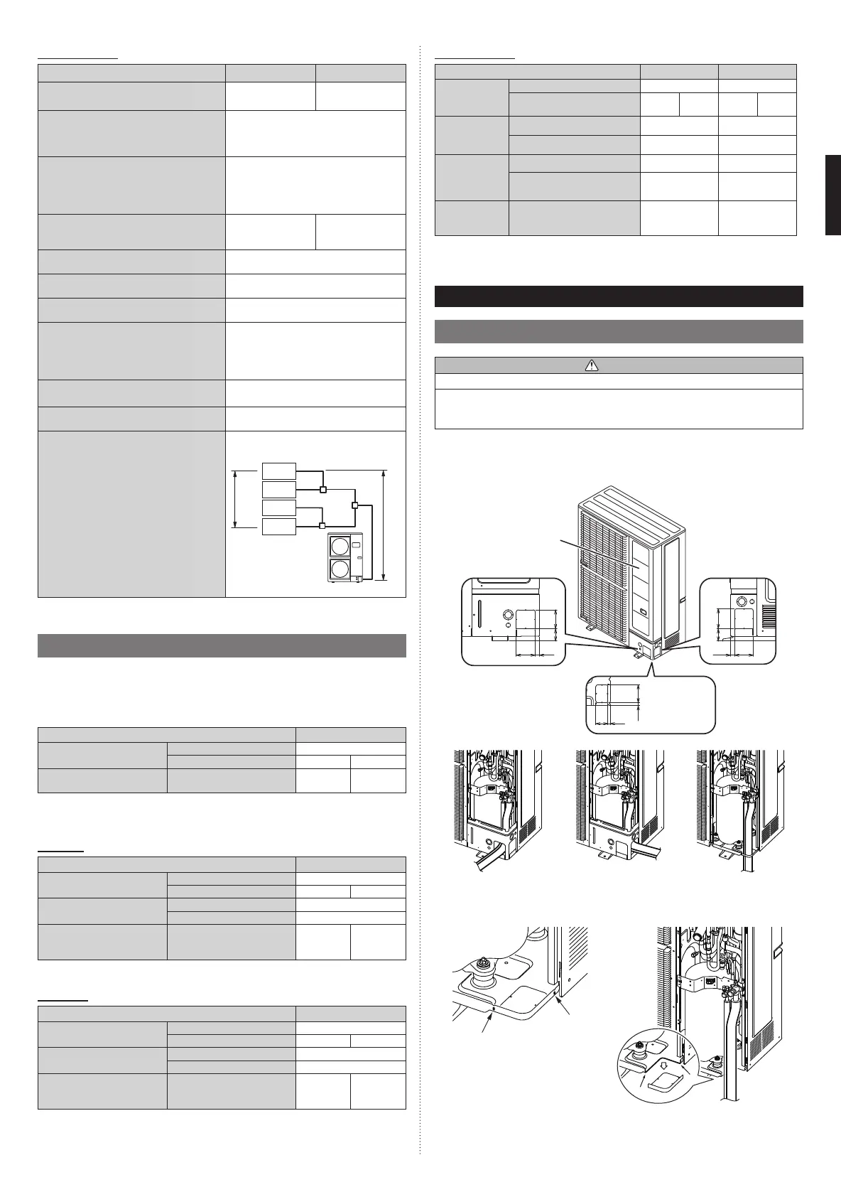
5.1. Opening a knock out hole
CAUTION
Be careful not to deform or scratch the panel while opening the knock out holes.
To protect the piping insulation after opening a knock out hole, remove any burrs from
the edge of the hole. It is recommended to apply rust prevention paint to the edge of
the hole.
• Pipes can be connected from 3 directions, front, lateral side and bottom. (Fig. A)
• When connecting at the bottom, remove the service panel and piping cover on the front
of the outdoor unit, and open the knockout hole provided at the bottom corner of the
piping outlet.
9221
61 100
94 21
61 94
60 12
14 90
Unit: mm
Fig. A
Service panel
Top view of
the base
Front connection Lateral connection Bottom connection
• It can be installed as shown on “Fig. B” cutting out the 2 slits as indicated on “Fig. C”.
(When cutting slits, use a steel saw.)
Slit
Slit
Fig. B
Bottom
connection
Fig. C
9380545231_IM.indb 69380545231_IM.indb 6 7/14/2017 8:53:11 AM7/14/2017 8:53:11 AM
 Loading...