En-7
5.2. Brazing
CAUTION
If air or another type of refrigerant enters the refrigeration cycle, the internal pressure in
the refrigeration cycle will become abnormally high and prevent the unit from exerting
its full performance.
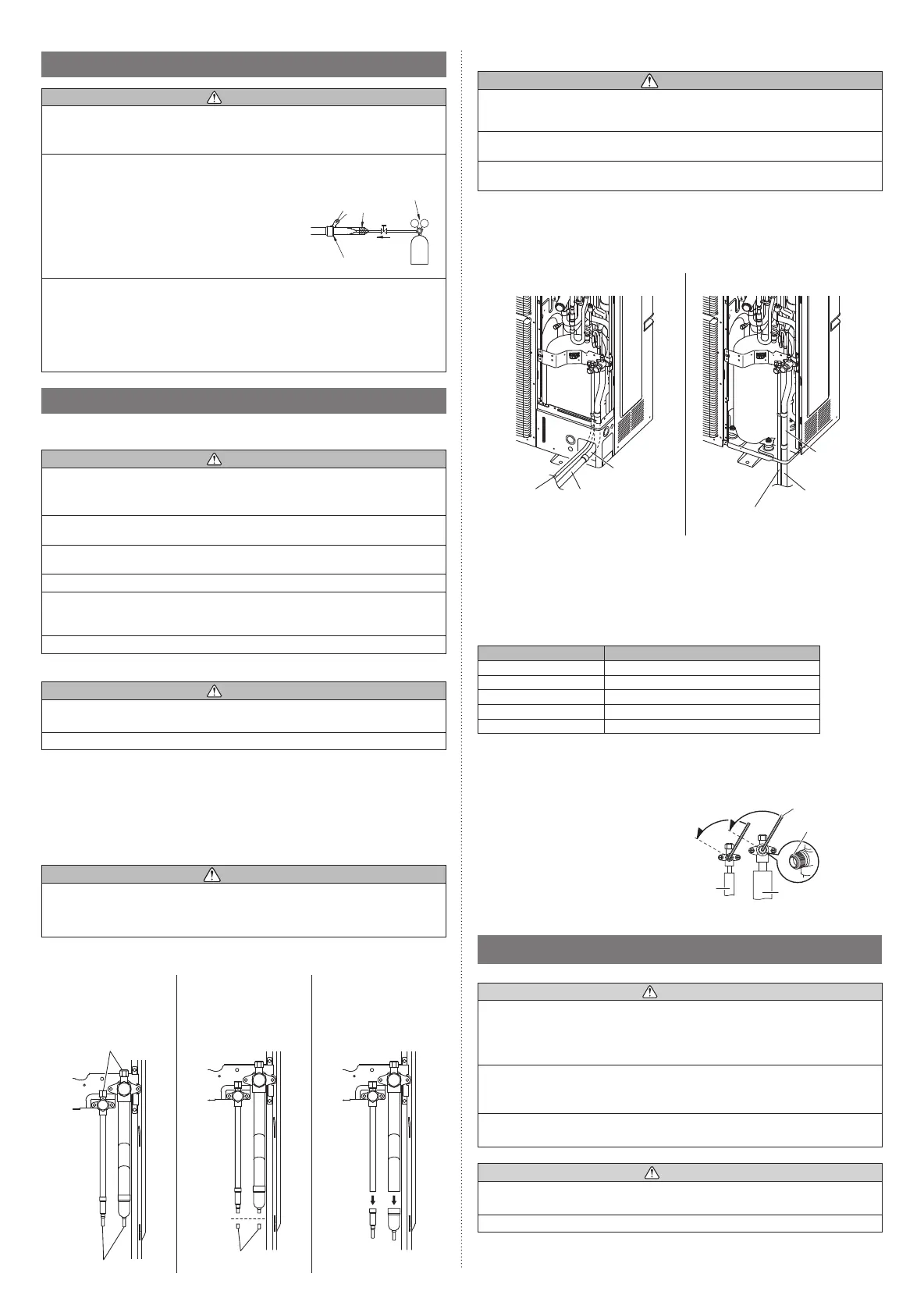
Apply nitrogen gas while brazing the pipes. If a pipe is brazed without applying nitro-
gen gas, an oxidation fi lm will be created.
This can degrade performance or damage the parts
in the unit (such as the compressor or valves).
Nitrogen gas pressure: 0.02 MPa
(= pressure felt suffi ciently on the back of the hand)
Pressure regulating valve
Cap
Brazing area
Nitrogen gas
For brazing material, use phosphor copper that does not require fl ux. Do not use fl ux to
braze pipes. If the fl ux is the chlorine type, it will cause the pipes to corrode.
Furthermore, if the fl ux contains fl uoride, it will adversely affect the refrigerant pipe
system such as by degrading the refrigerant.
If fl uoride is contained, quality of refrigerant deteriorates and affects the refrigerant
piping system.
5.3. Pipe connection
5.3.1. Precautions for connecting simultaneous operation multi
CAUTION
Use genuine branch pipes for the refrigerant piping branches. Branch pipes are twin or triple
type for concurrent operation, and may be used for piping between the outdoor and indoor
units.
Select a twin or triple type branch pipe and purchase it before starting the installation work.
Shorten the length of branch pipes from a branch to indoor unit as short as possible.
Maximum length: within 20 m.
Branch pipes shall be connected by welding (brazing).
Any vertical piping shall be in the part of the main piping. If a main pipe is bent, keep the
straight part more than 10 times the diameter of the connected pipe. A variance in the
amount of refrigerant may be caused if the straight part is short.
For details, refer to the Installation Manual of branch pipes.
5.3.2. Bending pipes
CAUTION
To prevent breaking of the pipe, avoid sharp bends. Bend the pipe with a radius of
curvature of 100 mm to 150 mm.
If the pipe is bent repeatedly at the same place, it will break
.
• If pipes are shaped by hand, be careful not to collapse them.
• Do not bend the pipes at an angle of more than 90°.
• When pipes are repeatedly bent or stretched, the material will harden, making it
diffi cult to bend or stretch them anymore.
• Do not bend or stretch the pipes more than three times.
5.3.3. Removing the pinch pipe
WARNING
Remove the pinch pipe only when the internal gas is completely drained as shown on
the below instructions.
If gas still remains inside, the piping may crack if you melt the brazing filler metal of the
junction area with a burner.
Before connecting the piping, remove the pinch pipe in accordance with the following
instructions:
1) Verify that the liquid
side and gas side 3-way
valves are closed.
2) Cut the end of the liquid
side and gas side pinch
pipe and vent the gas
inside the pinch pipe.
3) After all the gas is vented,
melt the brazing filler
metal on connecting part
using a torch and remove
the pinch pipe.
3-way valves
Pinch pipes
End of pinch pipes
5.3.4. Pipe connection
CAUTION
Seal the pipe route hole with putty (locally purchased) such that there are no gaps.
Small insects or animals that are trapped in the outdoor unit may cause a short circuit in
the electrical component box.
After completing all the pipe connection by brazing, perform the indoor unit pipe connec-
tion with a flare joint.
When removing the pinch pipe or brazing the joint pipe, carry out the work while cooling
down the 3-way valve sufficiently.
• Braze the joint pipe onto the 3-way valves at the liquid and gas side. Install the joint pipe
appropriately so that it can be connected easily with the main pipe.
• Braze the joint pipe at the liquid and gas side with the main pipe.
* Be sure to supply nitrogen when brazing.
Connection example (For Gas pipe φ22.22)
Front connection Bottom connection
Liquid pipe
(locally
purchased)
Gas pipe
(locally
purchased)
Joint pipe A
(accessory)
Liquid pipe
(locally purchased)
Gas pipe
(locally
purchased)
Joint pipe B
(accessory)
5.3.5. Handling precautions for the valves
• Mounted part of Blank cap is sealed for protection.
• Fasten blank cap tightly after opening valves.
Table A
Blank cap [mm (in.)] Tightening torque [N·m (kgf·cm)]
6.35 (1/4) 20 to 25 (200 to 250)
9.52 (3/8) 20 to 25 (200 to 250)
12.70 (1/2) 28 to 32 (280 to 320)
15.88 (5/8) 30 to 35 (300 to 350)
19.05 (3/4) 35 to 40 (350 to 400)
Operating the valves
• Use a hexagon wrench (size 3/16 in (4 mm)).
Opening:
(1) Insert the hexagon wrench into the
valve shaft, and turn it counterclock-
wise.
(2) Stop turning when the valve shaft can
no longer be turned. (Open position)
Closing:
(1) Insert the hexagon wrench into the
valve shaft, and turn it clockwise.
(2) Stop turning when the valve shaft can
no longer be turned. (Closed position)
Opening
direction
Hexagon wrench
Seal
(blank cap
installation
portion)
Liquid
pipe
Gas pipe
Opening
direction
5.4. Sealing test
WARNING
Before operating the compressor, install the pipes and securely connect them.
Otherwise, if the pipes are not installed and if the valves are open when the compressor
operates, air could enter the refrigeration cycle. If this happens, the pressure in the
refrigeration cycle will become abnormally high and cause damage or injury.
After the installation, make sure there is no refrigerant leakage. If the refrigerant leaks
into the room and becomes exposed to a source of fi re such as a fan heater, stove, or
burner, it produces a toxic gas.
Do not subject the pipes to strong shocks during the sealing test. It can rupture the
pipes and cause serious injury.
CAUTION
Do not block the walls and the ceiling until the sealing test and the charging of the
refrigerant gas have been completed.
For maintenance purposes, do not bury the piping of the outdoor unit.
9380545231_IM.indb 79380545231_IM.indb 7 7/14/2017 8:53:11 AM7/14/2017 8:53:11 AM
 Loading...