1. Connector failure connection
2. Thermistor failure
3. Controller PCB failure
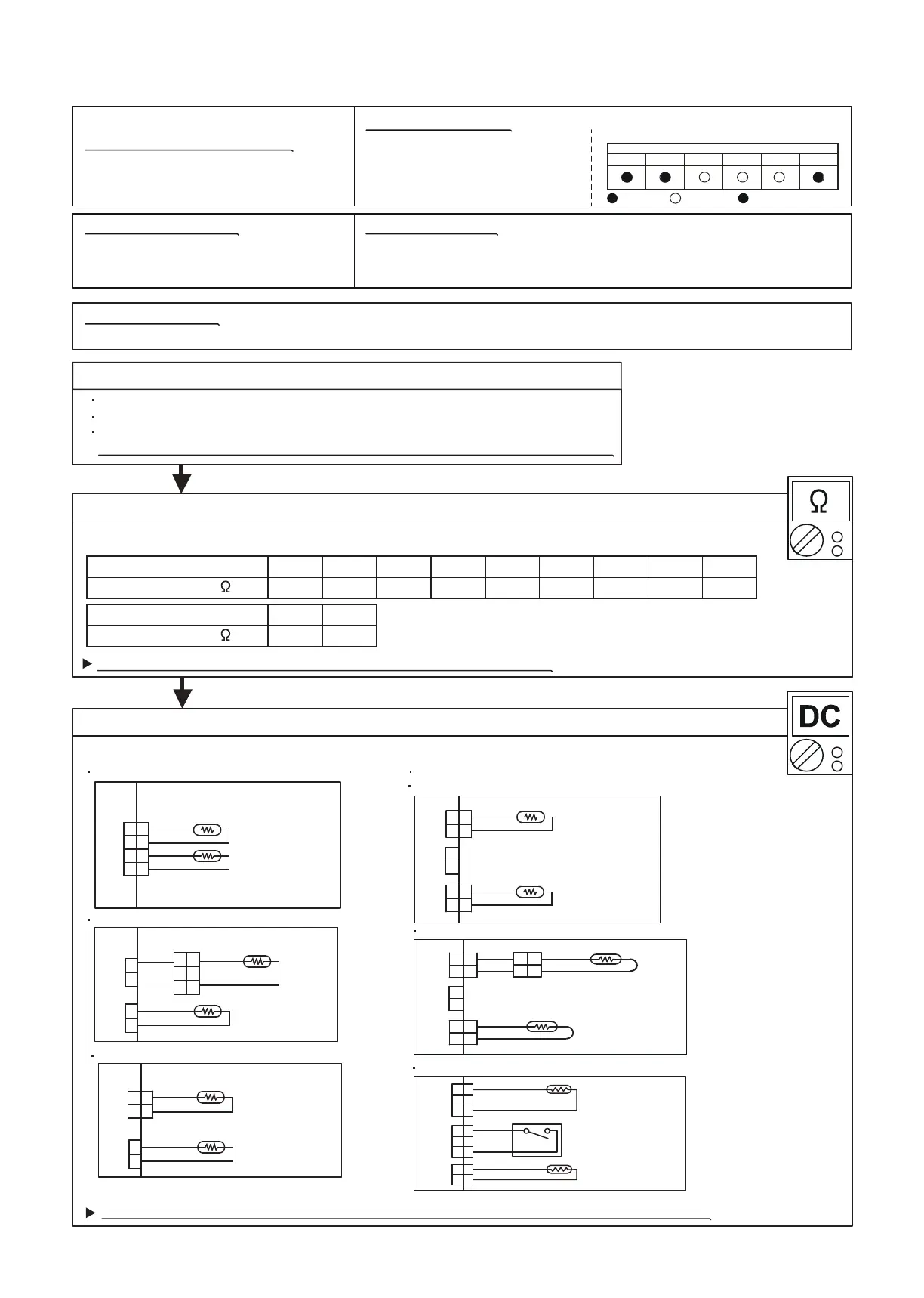
Test 2 : Remove connector and check Thermistor resistance value
Thermistor Characteristics (Rough value)
If Thermistor is either open or shorted, replace it and reset the power.
Test 1 : Check connection of Connector
Check if connector is loose or removed
Check erroneous connection
Check if thermistor cable is open
>>Reset Power when reinstalling due to removed connector or incorrect wiring.
OK
39.5762.91103.34176.03312.27579.591131.91
Resistance Value
(k )
30
25.64
40
17.06
5020100-10
-20-30Temperature (°C)
OK
Test 3 : Check voltage of Controller PCB (DC5.0V)
Make sure circuit diagram of each indoor unit and check terminal voltage at Thermistor (DC5.0V)
If the voltage does not appear, replace Controller PCB and execute the check operation again.
9.6911.64
Resistance Value
(k )
6560Temperature (°C)
Trouble shooting 13
INDOOR UNIT Error Method:
Indoor Heat Ex. Thermistor Error
Indoor unit controller PCB circuit
Heat exchanger thermistor
Heat exchanger thermistor is open or short is detected always.
Detective Actuators:
Detective details:
Indicate of Display:
Forecast of Cause:
02-28
Indoor Unit
Outdoor Unit
Operation lamp : 4 time Flash
ERROR CODE : [E : 42]
Timer lamp: 2 time Flash
: Light ON : Light OFF n : n time blinking
Compact wall mount circuit diagram(Connector connection)
H/E (MID) Thermistor
Room Temp. Thermistor
Room Temp. Thermistor
H/E Thermistor
Compact cassette circuit diagram (Connector connection)
Wall mount circuit diagram (Connector connection)
Slim duct circuit diagram (Connector connection)
BLACK
BLACK
3
4
CN4
1
2
3
4
1
2
BLACK
BLACK
BLACK
BLACK
BLACK
BLACK
1
2
1
2
CN3
CN1
1
2
3
1
2
3
RED
WHITE
H/E Thermistor
Room Temp. Thermistor
BLACK
BLACK
1
2
1
2
1 1
2 2
CN5
CN8
GRAY
GRAY
1
2
CN7
H/E (MID) Thermistor
Room Temp. Thermistor
BLACK
BLACK
1
2
1
2
1 1
2 2
CN5
CN8
GRAY
GRAY
1
2
CN7
1
2
1
2
BLACK
BLACK
Universal floor / ceiling circuit diagram (Connector connection)
Floor model circuit diagram (Connector connection)
GRAY
BLACK
BLACK
1
2
CN3
CN1
H/E Thermistor
Room Temp. Thermistor
1
2
1
2
GRAY
Monitor
A B C D E F
5 15
Float Switch
H/E (MID) Thermistor
Room Temp. Thermistor
BLACK
BLACK
1
2
3
1
2
3
1
2
3
1
2
1
2
1
2
3
GRAY
GRAY
Mini duct circuit diagram (Direct soldering to PCB)
CN6
CN8
CN9
 Loading...