REPLACEMENT PARTS
03-31
USED
PARTS
Fig.1
Through the hole.
W303 BLACK,W304 WHITE,W305 RED
(MAIN PCB)
WIRE WITH CONNECTOR
Through the guide.
BINDER C
INVERTER BOX A
BINDER C
Close up
Fig.2
Bind wire to
INVERTER BOX A.
Close up
The binder uniting part is a thing that
the base point line is not exceeded
18~20mm
Reference line
HOLDER(THERMO)
Installation position
Tumor part of INVERTER BOX A
INVERTER BOX A is
the highest
BINDER C
(COMP WIRE)
REGULATIONS
PROCESS
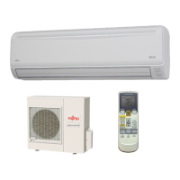
MODEL : AOU24RML
As shown in the figures, set WIRE WITH CONNECTOR and bind it to INVERTER BOX A.
The wire must not come in contact with the HOLDER(THERMO) SUS304 CSP-H T0.5
Bind WIRE WITH CONNECTOR
1
1
1
 Loading...

