Trouble shooting 1
INDOOR UNIT Error Method:
Detective Actuators:
Detective details:
Forecast of Cause:
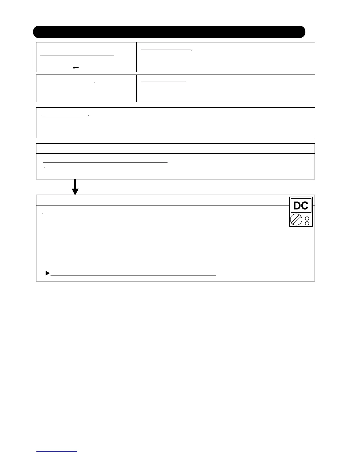
Check Point 2 : Check Remote Control and Control PCB
Check Point 1 : Check the connection of terminal
OKOK
Indicate or Display:
Refer to error code table.
Communication Error
(Indoor unit Remote control)
Indoor unit controller PCB circuit
Wired Remote Control
1. Terminal connection abnormal 2. Wired Remote Control failure 3. Control PCB failure (AS, AR)
After turning off the power, check & correct the followings.
Check the connection of terminal between remote control and Indoor unit,
and check if there is a disconnection of the cable.
Upon correcting the removed connector or mis-wiring, reset the power.
Check Voltage at CN10 (AS type) of Control PCB. (Power supply to Remote Control)
>> If it is DC12V, Remote Control is failure. (
Control PCB is normal) >> Replace Remote Control
>> If it is DC 0V,
Control PCB is failure. (Check Remote Control once again) >> Replace Control PCB (AS, AR)
Main PCB is failure. (Check Remote Control once again) >> Replace
Main PCB (AU)
When the indoor unit cannot receive the signal from Wired Remote
more than 10seconds after power ON, or the indoor unit cannot receive
the signal more than 1minute during normal operation.
02-08
2-2 TROUBLE SHOOTING WITH ERROR CODE
Main PCB (AU)
CN17 (AR type)
CN14 (AU type)