Pattern A
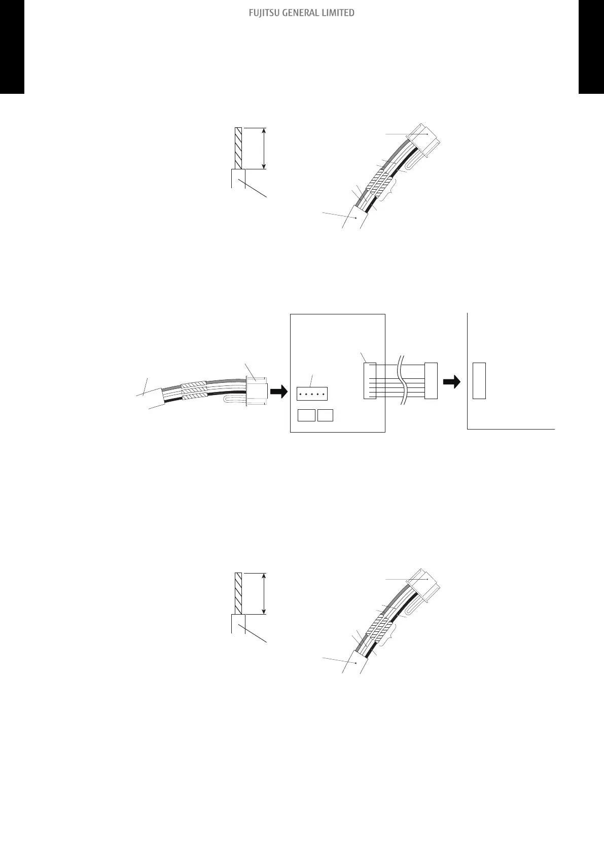
1. Modify the remote controller cable as follows:
• Use a tool to cut off the terminal on the end of the remote controller cable and then re-
move the insulation from the cut end of the cable as shown in following figure.
• Connect the remote controller cable and connecting cable as shown in following figure.
• Be sure to insulate the connection between the cables.
13/16 in.
(20 mm)
Remote controller cable
Connecting
cable
White
Red
White
Red
Black
Insulated
connection
Black
2. Connect the remote controller cable.
• Connect the cable made in step 1. to the terminal (*1) of optional communication kit.
• Connect the cable from the terminal (*2) of communication kit to the indoor unit PCB.
*1: CNC01 (for ASU7-15RLF1: UTY-XCBXZ2)
*2: CND01 (for ASU7-15RLF1: UTY-XCBXZ2)
Remote controller cable
Connecting cable Terminal
(*1)
Terminal
(*2)
Communication kit
Indoor unit PCB
Pattern B
1. Modify the remote controller cable as follows:
• Use a tool to cut off the terminal on the end of the remote controller cable and then re-
move the insulation from the cut end of the cable as shown in following figure.
• Connect the remote controller cable and connecting cable as shown in following figure.
• Be sure to insulate the connection between the cables.
13/16 in.
(20 mm)
Remote controller cable
Connecting
cable
White
Red
White
Red
Black
Insulated
connection
Black
- 179 -
15-7. Simple remote controller (UTY-RSNUM: Optional part) 15. Remote controller
MULTI-SPLIT TYPE
5-unit type
MULTI-SPLIT TYPE
5-unit type

 Loading...