4
Fig. 5 Remote Control Unit
B SLEEP button
C MASTER CONTROL button
D SET TEMP./SET TIME buttons (
)
E Signal Transmitter
F TIMER button
G FAN CONTROL button
H START/STOP button
I AIR FLOW DIRECTION SET button
J AIR FLOW DIRECTION SWING button
K TIME ADJUST button
L ACL button
Rear side (Fig. 6)
M TEST RUN
● Touch the two metal contacts with a me-
tallic object to send the signal to perform
a test run.
● Perform a test run only when installing the
air conditioner. If the signal to perform a
test run is received during normal opera-
tion, the air conditioner’s thermostat will
malfunction.
● If the signal to perform a test run is re-
ceived during normal operation, the unit
will switch to the test operation mode and
the indoor unit’s OPERATION and TIMER
indicator lamps will flash simultaneously.
● To stop the test operation mode, press the
START/STOP button to stop the air condi-
tioner.
N Remote Control Unit Display (Fig. 7)
O Transmit Indicator
P Clock Display
Q Operating Mode Display
R T imer Mode Display
S Fan Speed Display
T Temperature Set Display
U T imer Set Indicator
V Temperature Set Indicator
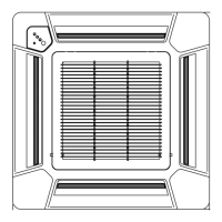
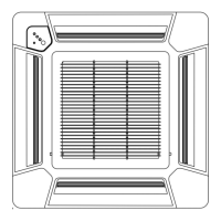
Fig. 1 Indoor Unit
1 Air Filter
2 Horizontal Louvers
3 Indicator Lamps (Fig. 2)
4 SWING Indicator Lamp (orange)
Lights during use of the SWING.
5 TIMER Indicator Lamp (green)
Lights during use of the ON timer, OFF timer,
PROGRAM timer, and SLEEP timer.
6 OPERATION Indicator Lamp (red)
● Lights when unit is in operation.
● Flashes quickly for about one second when
a signal is received from the remote con-
trol unit.
[When the OPERATION indicator and TIMER
indicator flash alternately, it means that the
power has been interrupted due to a power
failure, etc.]
7 Remote Control Signal Receiver
8 MANUAL AUTO Button
9 Air Intake Grille
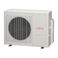
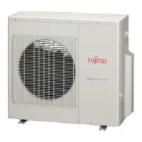
Fig. 3 Outdoor Unit
; Intake Port
A Outlet Port