Do you have a question about the Fujitsu AUXB07GALH and is the answer not in the manual?
Procedures and precautions for test run execution.
Outlines methods for conducting test runs.
Details control parameters and procedures for test runs.
Lists field settings and monitor modes for outdoor units.
Details field settings and functions for indoor units.
Details field settings and functions for outdoor air units.
Lists inputs and outputs for the outdoor unit.
Details compressor operation modes, capacity control, and speed ranges.
Explains fan control for cooling and heating operations.
Details control of expansion valves for cooling and heating.
Covers oil recovery, pre-heat, and defrost operations.
Lists and describes various protective functions and their operating conditions.
Details fan speed settings and automatic position control for cooling and heat.
Covers operation mode control, priority modes, and auto changeover.
Details adjustment of air circulation direction and swing operations.
Details initialization, operation, and special control of electronic expansion valves.
Explains drain pump operation during cooling, heating, and fault conditions.
Covers auto restart, icing protection, and oil recovery functions.
Explains timer functions for wireless, group, and wired remote controllers.
Covers DX-KIT system configuration and fundamental functions.
Describes normal operation indicators and display patterns for indoor and outdoor units.
Provides troubleshooting for abnormal operation via error codes and displays.
Provides systematic troubleshooting steps for various error conditions.
Shows the refrigerant circuit diagram for different models.
Explains symbols used in refrigerant and wiring diagrams for outdoor and indoor units.
Provides wiring diagrams for various indoor unit types.
Provides characteristic data for pressure sensors and thermistors.
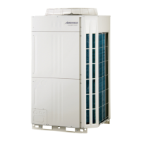
Shows visual appearance of the outdoor unit.
Steps for removing the service panel.
Instructions for removing the main PCB.
Steps for removing the communication PCB.
Procedures for removing power, inverter, filter, and diode bridge PCBs.
Procedures for removing fan driver and inverter CT PCBs.
Steps for removing pressure sensors and solenoid coils.
Steps for removing the EEV coil.
Steps for removing thermistors.
Detailed steps for removing the fan motor.
Steps for removing the top panel.
Steps for removing the reactor.
Steps for removing the pipe cover front.
Steps for removing the right panel.
Detailed procedure and precautions for compressor removal.
Safety precautions for exchanging refrigerant cycle parts.
| Brand | Fujitsu |
|---|---|
| Model | AUXB07GALH |
| Category | Air Conditioner |
| Language | English |