En-4
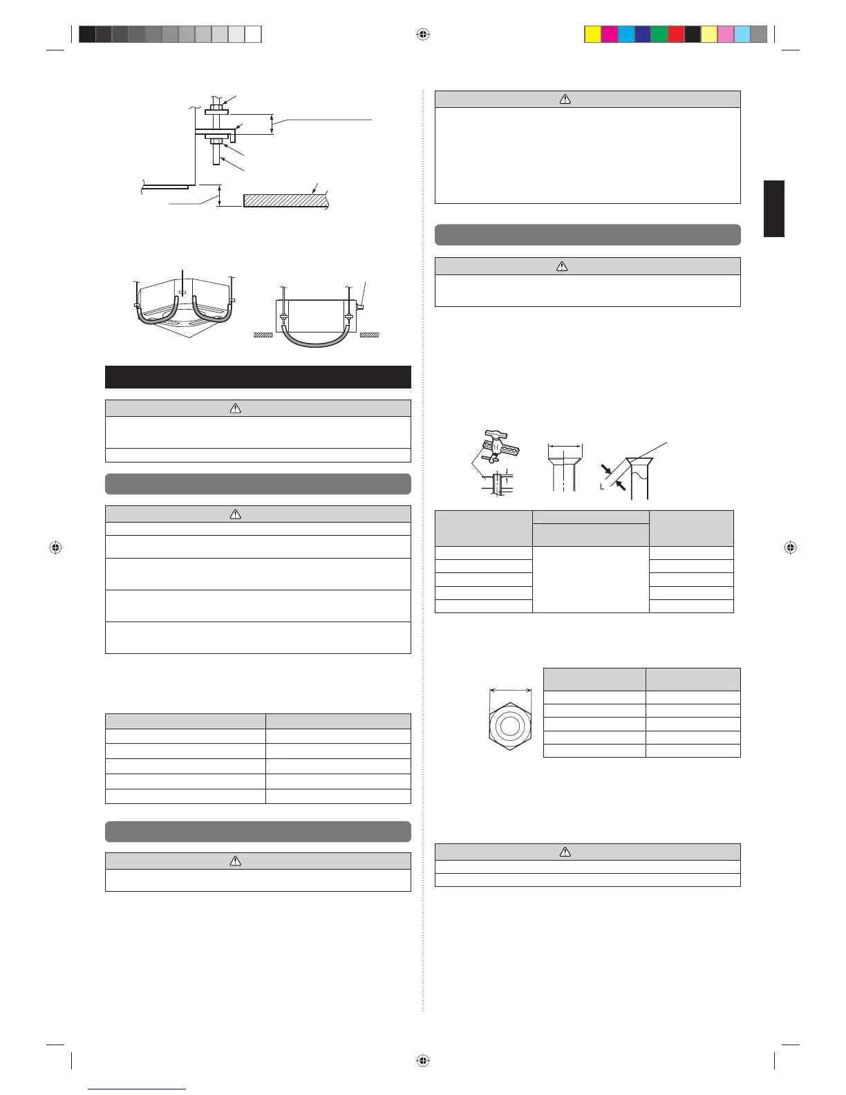
Special nut A
Special nut B
Hook
Hanging bolt
30 mm or more
After installing the body,
tighten the nuts.
17 mm
Ceiling
Indoor unit
Leveling
• Using a level, or vinyl hose fi lled with water, fi ne adjust so that the body is level.
• Inclined installation so as the drain pipe side is higher may cause a malfunction of the
fl oat switch, and may cause water leakage.
Vinyl hoses
Drain pipe
4.
PIPE INSTALLATION
CAUTION
Be more careful that foreign matter (oil, water, etc.) does not enter the piping than with
refrigerant R410A models. Also, when storing the piping, securely seal the openings by
pinching, taping, etc.
While welding the pipes, be sure to blow dry nitrogen gas through them.
4.1. Selecting the pipe material
CAUTION
Do not use existing pipes from another refrigeration system or refrigerant.
Use pipes that have clean external and internal sides without any contamination which
may cause trouble during use, such as sulfur, oxide, dust, cutting waste, oil, or water.
It is necessary to use seamless copper pipes.
Material : Phosphor deoxidized seamless copper pipes
It is desirable that the amount of residual oil is less than 40 mg/10 m.
Do not use copper pipes that have a collapsed, deformed, or discolored portion
(especially on the interior surface). Otherwise, the expansion valve or capillary tube may
become blocked with contaminants.
Improper pipe selection will degrade performance. As an air conditioner using R410A
incurs pressure higher than when using conventional (R22) refrigerant, it is necessary to
choose adequate materials.
• Thicknesses of copper pipes used with R410A are as shown in the table.
• Never use copper pipes thinner than those indicated in the table even if they are
available on the market.
Thicknesses of Annealed Copper Pipes (R410A)
Pipe outside diameter [mm (in.)] Thickness [mm]
6.35 (1/4) 0.80
9.52 (3/8) 0.80
12.70 (1/2) 0.80
15.88 (5/8) 1.00
19.05 (3/4) 1.20
4.2. Pipe requirement
CAUTION
Refer to the installation manual for the outdoor unit for description of allowable pipe
length and height difference.
Use pipe with water-resistant heat insulation.
CAUTION
Install heat insulation around both the gas and liquid pipes. Failure to do so may cause
water leaks.
Use heat insulation with heat resistance above 120 °C. (Reverse cycle model only)
In addition, if the humidity level at the installation location of the refrigerant piping is
expected to exceed 70 %, install heat insulation around the refrigerant piping. If the
expected humidity level is 70 to 80 %, use heat insulation that is 15 mm or thicker and
if the expected humidity exceeds 80 %, use heat insulation that is 20 mm or thicker. If
heat insulation is used that is not as thick as specifi ed, condensation may form on the
surface of the insulation. In addition, use heat insulation with heat conductivity of 0.045
W/(m·K) or less (at 20 °C).
4.3. Flare connection (pipe connection)
WARNING
Tighten the flare nuts with a torque wrench using the specified tightening method.
Otherwise, the fl are nuts could break after a prolonged period, causing refrigerant to
leak and generate hazardous gas if the refrigerant comes into contact with a fl ame.
4.3.1. Flaring
Use special fl are tool exclusive for R410A.
(1) Cut the connection pipe to the necessary length with a pipe cutter.
(2) Hold the pipe downward so that cuttings will not enter the pipe and remove any burrs.
(3)
Insert the fl are nut (always use the fl are nut attached to the indoor and outdoor units (or
RB unit) respectively) onto the pipe and perform the fl are processing with a fl are tool. Use
the special R410A fl are tool. Leakage of refrigerant may result if other fl are nuts are used.
(4) Protect the pipes by pinching them or with tape to prevent dust, dirt, or water from
entering the pipes.
Pipe
A
Die
B
Check if [L] is fl ared uniformly and
is not cracked or scratched.
Pipe outside diameter
[mm (in.)]
Dimension A [mm]
Dimension B
-
0
0.4
[mm]
Flare tool for R410A,
clutch type
6.35 (1/4)
0 to 0.5
9.1
9.52 (3/8) 13.2
12.70 (1/2) 16.6
15.88 (5/8) 19.7
19.05 (3/4) 24.0
When using conventional (R22) fl are tools to fl are R410A pipes, the dimension A should
be approximately 0.5 mm more than indicated in the table (for fl aring with R410A fl are
tools) to achieve the specifi ed fl aring. Use a thickness gauge to measure the dimension A.
It is recommended that a R410A fl aring tool is used.
Width across
fl ats
Pipe outside
diameter [mm (in.)]
Width across flats
of Flare nut [mm]
6.35 (1/4) 17
9.52 (3/8) 22
12.70 (1/2) 26
15.88 (5/8) 29
19.05 (3/4) 36
4.3.2. Bending pipes
• If pipes are shaped by hand, be careful not to collapse them.
• Do not bend the pipes in an angle more than 90°.
• When pipes are repeatedly bend or stretched, the material will harden, making it
diffi cult to bend or stretch them any more.
• Do not bend or stretch the pipes more than 3 times.
CAUTION
To prevent breaking of the pipe, avoid sharp bends.
If the pipe is bent repeatedly at the same place, it will break.
9371022253-01_IM.indb Sec1:49371022253-01_IM.indb Sec1:4 2012-7-12 14:34:412012-7-12 14:34:41
 Loading...