Pin assignment of internal ports
10 - English A26361-D1451-Z120-1-6319
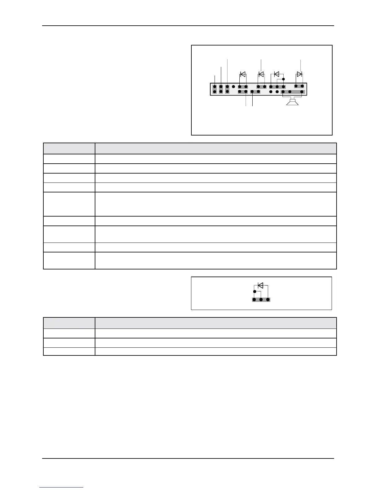
Bedienfeld / Front panel
Watch the poling of the LEDs. The positive pole
of the connection cables is often indicated with a
coloured wire.
1
2
HD-LED
1)
Power On/Off
SCSI LED Input
2)1)
1)
Sleep
Reset
1)
Power On
LED
1) 3)
Sleep LED
Speaker
Message LED
1)
1) Cable is not included in the delivery scope.
2) The same interface
3) 2pin or 3pin connector possible
Connection Note
Reset
Sleep This connection is reserved for future use.
Power On/Off
HD LED
SCSI Activity
Input
Attention: Do not connect to the LED connections of an SCSI controller! This
connection is intended for a cable with a 4-pin connector. An SCSI controller
reports activity (low-active) via this cable.
Message LED
Power On LED
I
Indicates the system state APM or ACPI together with the Sleep LED (see
chapter entitled "APM and ACPI system status, energy-saving modes").
Speaker 0,5 W at 8 Ohm
Sleep
LED
Indicates the system state APM or ACPI together with the Power-On LED (see
chapter entitled "APM and ACPI system status, energy-saving modes").
Power On LED II
1
3
Pin Note
1 Power On LED (Anode)
2 Power On LED (Anode)
3 Power On LED (Cathode)