A26361-D1451-Z120-1-6319 Umschlag/Cover
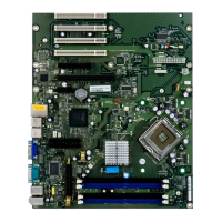
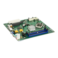
Übersicht/Overview mainboard D1522/D1521
Interne Anschlüsse und Steckplätze / internal
connectors and slots
1
2
3
4
5
7
8
9
10
11
12
13
14
15
16
6
D I M M 1
D I M M 2
PCI 1
PCI 2
PCI 3
CNR
1 = Stromversorgung / Power
Supply
2 = Bedienfeld / Frontpanel
3 = PowerOn LED II
4 = Diskettenlaufwerk / Floppy disk
drive
5 = IDE-Laufwerke 3/4 / IDE-drives
3/4
6 = IDE-Laufwerke 1/2 / IDE-drives
1/2
7 = Batterie / Battery
8 = USB E/F
9 = Schalter / Configuration Switch
10 = Lüfter 2 / Fan 2
11 = CD audio in
12 = Audio Bedienfeld / Audio
Frontpanel
13 = S/PDIF Anschluss / S/PDIF
Connector
14 = Zweite serielle Schnittstelle /
Second serial port
15 = Stromversorgung Prozessor /
Power supply processor
16 = Lüfter 1 / Fan 1
Optionale Komponenten / Optional
components
Externe Anschlüsse / External connectors
LAN
AUDIO
PowerOn LED II
3)
1)
1
3
1
2
HD-LED
1)
Power On/Off
SCSI LED Input
2)1)
1)
Sleep
Reset
1)
Power On
LED
1) 3)
Sleep LED
Speaker
Message LED
1)
1) Cable is not included in the delivery scope.
2) The same interface
3) 2pin or 3pin connector possible