D2759 (TX150 S7) Technical Manual 31
Features Connectors and indicators
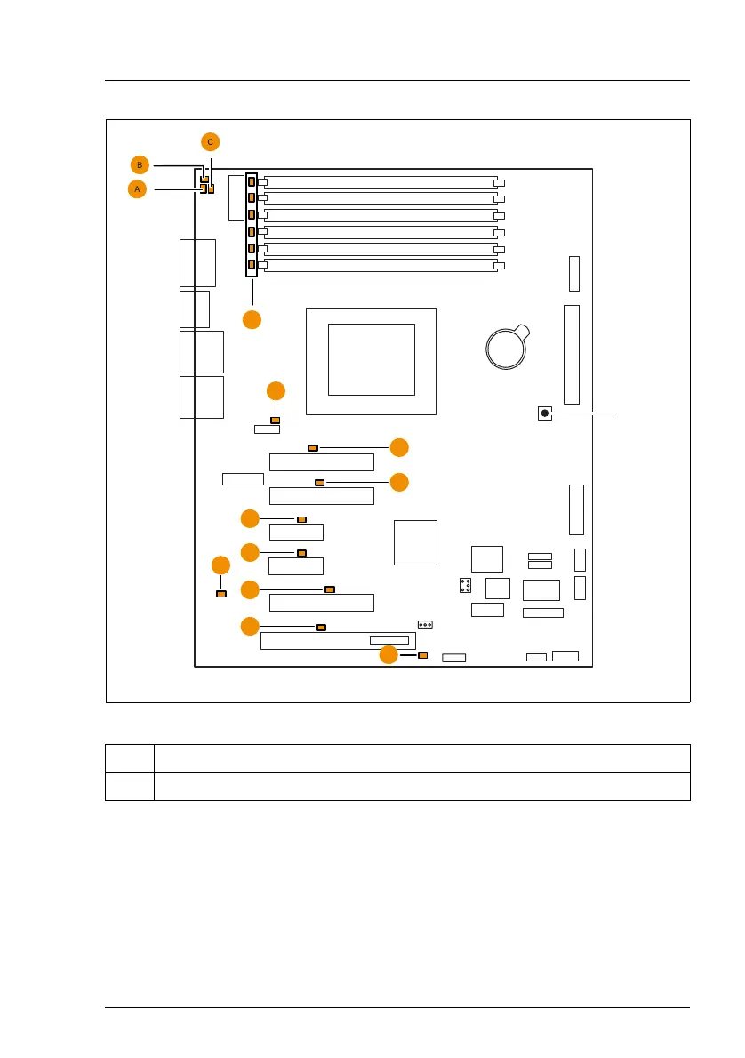
Figure 6: Indicators on the system board and CSS indicate button
LEDs A, B and C are visible from outside on the rear of the server. All the other
LEDs are only visible, if the cover of the server has been opened. For CSS
LED´s of the memory modules the air duct (including system fan) has to be
removed.
If the server has been powered off (power-plugs must be disconnected) it is
possible to indicate the faulty component by pressing the CSS indicate button.
No. Description
1 CSS indicate button
VGA
Slot 3
Slot 2
Slot 1
DIMM1B
DIMM2B
DIMM3B
DIMM1A
DIMM2A
DIMM3A
Battery
External connectors
Slot 4
Slot 5
Slot 6
Serial 1
Service
LAN 1
USB 3/4
ATX PWR1
ATX12V1
FAN1 SYS
Frontpanel
Intrusion
PC98
SATA5 SATA6
SATA
MLC
PCIe x8 Gen2
PCIe x4
System
LAN 2
USB 5/6
PCIe x8 Gen2
Serial 2
CPU
PCIe x1
PCI 32 Bit / 33 MHz
SMB1
USB
Front
USB SSD
TPM
USB
stick
PCIe x1
USB2 AUX
USB1 AUX
HDD Activity
E
D
F
F
F
F
F
F
H
G
Reset
Configuration
jumper
0
CSS
indicate
button