D2759 (TX150 S7) Technical Manual 33
Features Connectors and indicators
3.6.2 Connector panel
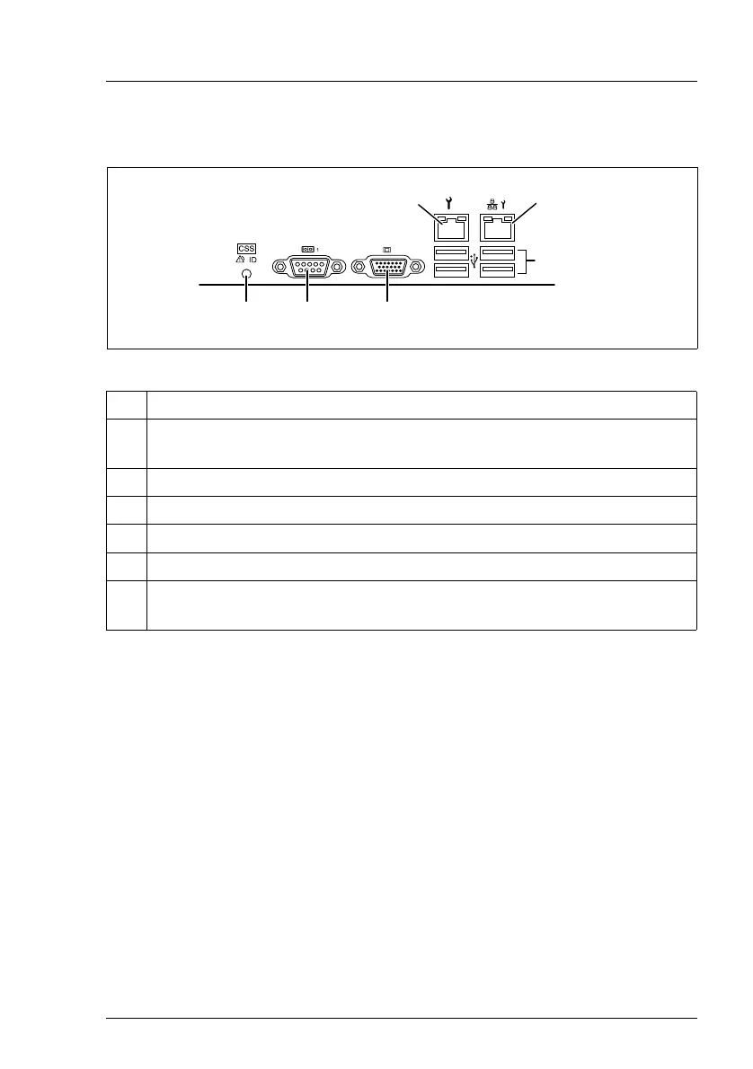
Figure 7: Connector panel
Depending on the settings in the BIOS, the system LAN connector may also be
used as a service LAN connector. You will find further information in the "D2759
BIOS Setup Utility for PRIMERGY TX150 S7" manual.
The serial connector COM1 can be used as default interface or to communicate
with the iRMC S2.
I The chip set has two integrated USB 2.0 hubs, the Rate Matching Hubs
(RMHs). The bandwidth for USB 1.1 Full Speed Devices for each RMH
is 12 Mbit/s, the bandwidth for High Speed Devices being 480 Mbit/s.
This means that fewer memory accesses are required, thereby placing
the CPU more effectively in low power status.
No. Description
1 Service LAN connector (LAN 1), for iRMC S2 server management
function
2 System LAN connector (LAN 2)
3 USB connectors
4 Video connector (VGA)
5 Serial connector COM1
6 Global error indicator (orange), CSS indicator (yellow), ID indicator
(blue); (description see preceding section)
/
0
1
23
4