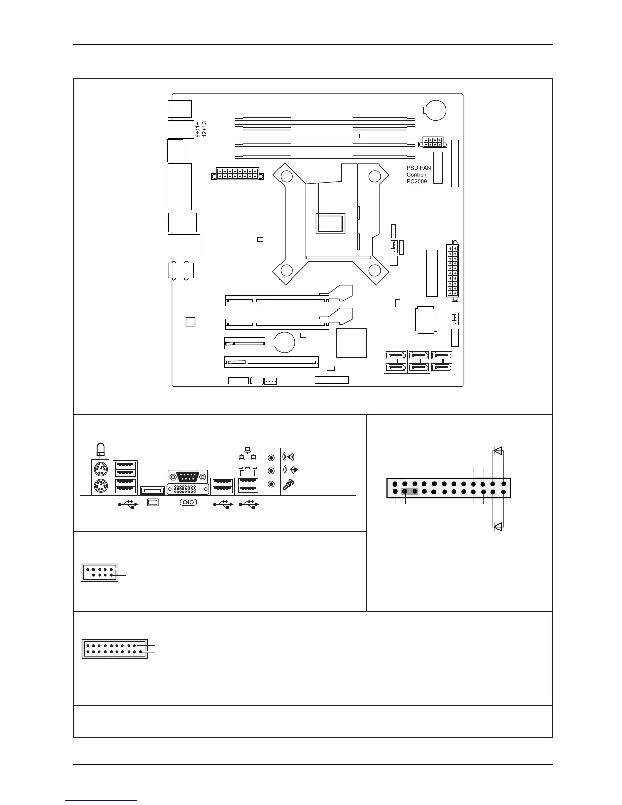
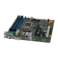
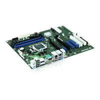
Internal connectors and slots
External connectors rear
1
2
1 = 5V USB
2 = 5V USB
3 = Data negative Port X
4 = Data negative Port Y
6 = Data positive Port Y
Data positive Port X
7 =
5 =
GND
8 = GND
9 = Key
10 = Not connected
Front panel
Recovery inserted = The system starts
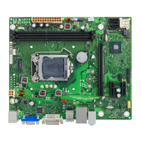
DVI-I
Channel B, Slot 2
Channel B, Slot 4
Channel A, Slot 1
Channel A, Slot 3
Battery
Audio PS2
COM
DVI-I
Display
Port
USB
USB
3.0
0+1
6+7
2.0
2.0
PCI
PCIe4(16)
Intrusion
FAN1
FAN2
HDD Power
Frontpanel
Audio
Frontpanel
SATA
0+1
SATA
4+5
SATA
2+3
Power Supply
USB
8+10
FAN 3
Parallel Port
PCIe16
PCIe1
Super
I/O
Power Supply
Connector OEM
TPM Enable
Temp. Sensor
Temp. Sensor
Temp. Sensor
USB
4+5
Desc Override
Enable
Intel-LAN
1
2
HD-LED
Recovery
Reset
Power
On/Off
Power LED
LAN
USB
from USB stick and allows a BIOS recovery.
Details can be found in the BIOS manual.
A26361-D3161-Z320-1-7419
Battery
CPU
LGA1155
USB 3.0
1 = 5V USB
2 = USB3_RX negative (P2)
3 = USB3_RX positive (P2)
4 = GND
USB3_TX negative (P2)
5 =
19
1
6 = USB3_TX positive (P2)
7 = GND
8 = Data negative (P2)
9 = Data positive (P2)
10 = FP Detect
11 = Data positive (P3)
12 =
Data negative (P3)
13 = GND
14 = USB3_TX positive (P3)
USB3_TX negative (P3)
15 =
16 = GND
17 = USB3_RX positive (P3)
18 = USB3_RX negative (P3)
19 = 5V USB
20 = Not connected
USB 3.0
2+3
PCH
USB 2.0
USB 3.0
Fujitsu Technology Solutions