9
4.2 Choosing a Location
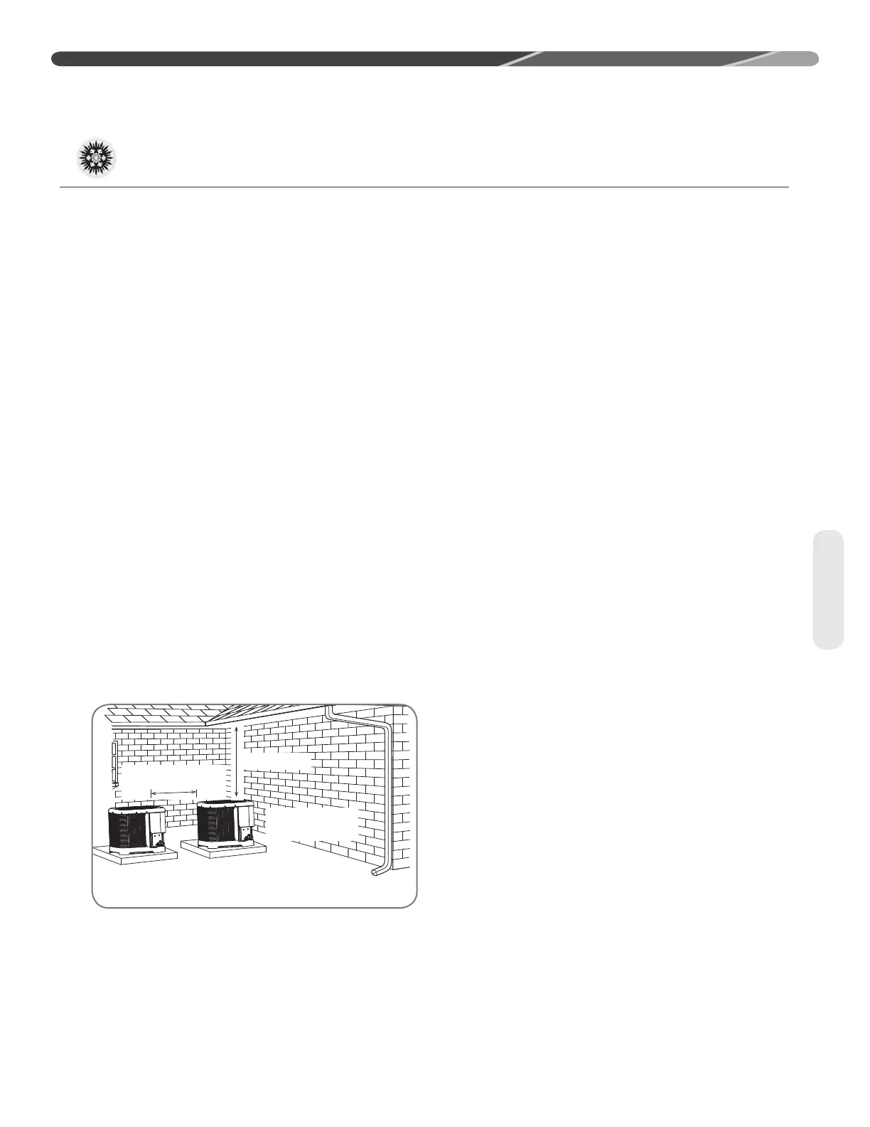
4.2.1 Allowable Clearances
WRVLGHLQWDNHORXYHUV
24" to service access panels
60" vertical for fan discharge
,IVSDFHOLPLWDWLRQVH[LVWWKHIROORZLQJFOHDUDQFHV
ZLOOKDYHPLQLPDOLPSDFWWRFDSDFLW\DQGHIILFLHQF\
and are permitted:
Single-Unit Applications: Minimum of 6" to side
LQWDNHORXYHUV'RQRWUHGXFHWKH>FP@
for fan discharge or the 24" [61.0 cm] service
clearances.
Multiple-Unit Applications: For units positioned
next to each other, a minimum of 6" [15.2 cm]
FOHDUDQFHEHWZHHQXQLWVLVUHFRPPHQGHGIRU
and 2 ton models and 9" [22.9 cm] for 2.5 ton to
5 ton models. Do not reduce the 60" [152.4 cm]
for fan discharge or the 24" [61.0 cm] service
clearances.
IMPORTANT: Consult local and
national building codes and ordinances for special
LQVWDOODWLRQUHTXLUHPHQWV)ROORZLQJORFDWLRQ
LQIRUPDWLRQZLOOSURYLGHORQJHUOLIHDQGVLPSOLILHG
servicing of the outdoor heat pump.
NOTICE: These units must be installed
RXWGRRUV1RGXFWZRUNFDQEHDWWDFKHGRURWKHU
modifications made, to the discharge grille.
0RGLILFDWLRQVZLOODIIHFWSHUIRUPDQFHRURSHUDWLRQ
4.2.2 Operational Issues
Related to Unit Location
IMPORTANT: Locate the unit in a
PDQQHUWKDWZLOOQRWSUHYHQWLPSDLURUFRPSURPLVH
the performance of other equipment installed
in proximity to the unit. Maintain all required
minimum distances to gas and electric meters,
dryer vents, and exhaust and inlet openings. In
WKHDEVHQFHRIQDWLRQDOFRGHVRUPDQXIDFWXUHUV·
recommendations, local code recommendations
DQGUHTXLUHPHQWVZLOOWDNHSUHFHGHQFH
5HIULJHUDQWSLSLQJDQGZLULQJVKRXOGEHSURSHUO\
VL]HGDQGNHSWDVVKRUWDVSRVVLEOHWRDYRLG
capacity losses and increased operating costs.
/RFDWHWKHXQLWZKHUHZDWHUUXQRIIZLOOQRWFUHDWH
DSUREOHPZLWKWKHHTXLSPHQW3RVLWLRQWKHXQLW
DZD\IURPWKHGULSHGJHRIWKHURRIZKHQHYHU
SRVVLEOH8QLWVDUHZHDWKHUL]HGEXWFDQEH
DIIHFWHGE\WKHIROORZLQJ
• Water pouring into the unit from the junction
RIURRIOLQHVZLWKRXWSURWHFWLYHJXWWHULQJ/DUJH
YROXPHVRIZDWHUHQWHULQJWKHKHDWSXPSZKLOH
in operation can impact fan blade or motor life,
and coil damage may occur to a heat pump if
moisture cannot drain from the unit under freezing
conditions.
• Freezing moisture or sleeting conditions can
cause the cabinet to ice-over prematurely and
SUHYHQWKHDWSXPSRSHUDWLRQUHTXLULQJEDFNXS
KHDWZKLFKJHQHUDOO\UHVXOWVLQOHVVHFRQRPLFDO
RSHUDWLRQ,WLVKLJKO\UHFRPPHQGHGWRVZLWFKWKH
EcoNet™ Control Center or thermostat to the
"Emergency Heat" mode during freezing rain
or sleeting conditions to prevent damage to the
outdoor coil from ice accumulating on the fan
blade.
&ORVHO\IROORZWKHFOHDUDQFHUHFRPPHQGDWLRQVLQ
Section 4.2.1.
• 24" [61.0 cm] to the service panel access
• 60" [152.4 cm] above heat pump fan discharge
(unit top) to prevent recirculation
• 6" [15.2 cm] to heat pump coil grille air inlets
ZLWK>FP@PLQLPXPUHFRPPHQGHG
SERVICE PANELS/
INLET CONNECTIONS
/ HIGH & LOW
VOLTAGE ACCESS
ALLOW 24” [610 mm] OF
CLEARANCE
ALLOW 60” [1524 mm]
OF CLEARANCE
AIR INLET LOUVERS ALLOW
6” [152 mm] Min. OF
CLEARANCE ALL SIDES
12” [305 mm] RECOMMENDED
ST-A1226-04-00
6" MIN. (152 mm) FOR 1.5 & 2 TON
9" MIN. (229 mm) FOR 2.5-5 TON
24" MIN. (610 mm)
4.0 INSTALLATION
Location