Normal
display
Normal
display
Filter sign
display
The meshes of the filter were
clogged up.
Check if the filter is dirty.
Controlling
(Operation
display LED
flashes)
(Oil recovery
operation)
Normal
display
Error display
(Indoor unit
fan error)
Normal
display
Error display
error)
Error display
Normal
display
Normal
display
or
temperature
error)
Normal
display
(Indoor unit
error)
(Thermistor
(Discharge
Body
LED
LCD
Symptom that
can occur other
than title
Check method
(Error state check method)
Remarks
Cause
display
Controlling
display
System does
not cool/heat.
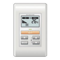
When the operating time of fan
motor of any indoor unit exceeds
150 hours, the filter cleaning sign
appears at the wired remote
controller.
The operating time of fan motor
can be reset by pushing the
ZONE/SET button for more than
3 seconds.
The filter cleaning sign is in-
formed by flashing of the set
temperature display(1 sec. ON,
1 sec. OFF and repeat).
Oil recovery operation control is
in progress.
All indoor unit fans stop and the
signal sent from remote control-
ler is not accepted by indoor unit.
1st oil recovery operation: 1 hour
Operation LED flashes (3 sec.
ON, 1 sec. OFF and repeats).
Check the resistance value of
the capacitor.
(If normal, the resistance will
show a value of several hundred
kilohms.)
Indoor fan capacitor is faulty.
Indoor fan motor is faulty.
Indoor unit thermistor is faulty.
Large ceiling type, slim body cas-
sette type and ceiling wall type
will inform the error.(Others don't)
Check the fan motor resistance
or voltage.
Measure the thermistor
resistance and compare it to
the ambient temperature.
Refer to section 7-2-1 for the
temperature and thermistor
resistance relationship.
When thermistor shorted
or open, error occurs.
Indoor unit short circuit.
Indoor control PCB is faulty.
Outdoor control PCB is faulty.
System does
not cool/heat.
Cannot be
specified.
Cannot be
specified.
(Cannot be
specified.)
Cannot be
specified
Air flow out from an indoor
unit is sucked directly into the
same indoor unit or into another
indoor unit.
Symptom has many branches,
depending on the error contents,
and there is no effective check
method.
If the problem is caused by PCB
or connection wire the trouble is
often sloved by a change of PCB
or connection wire.
Symptom has many branches,
depending on the error contents,
and there is no effective check
method.
No display
or
05-37
Error display
(Indoor unit
fan error)
Error display
error)
(Thermistor
Error display
Error display
(Cannot be
specified.)
No display
or
Error display
(Cannot be
specified.)
No display
or
Error display
System does
not cool/heat.
Abnormal
sound
is heard from
indoor unit.
(operation time) after the power
turned on. 2nd oil recovery opera-
tion and afterwards: every 6
hours (operation time).
If the problem is caused by PCB
or connection wire the trouble is
often sloved by a change of PCB
or connection wire.
Abnormal sound
is heard from
indoor unit.
System does
not cool/heat.
Abnormal
sound
is heard from
indoor unit.
Warning:
1) For large ceiling model or slim
body cassette model, perform ch-
eck by following procedures:
(1)Turn off the power of indoor
unit. Wait for several minutes.
(2)Disconnect the plug from PCB.
(3)Fully discharge the electricity
before doing check.
(4)Check the resistance of capa-
citor for large ceiling or slim body
cassette. 1-2 of terminal CN3.
(5)Check the motor resistance:
For large ceiling model, check re-
sistances (4-5, 5-6) of CN4.
For slim body cassette model,
check resistances (5-6, 5to1,2,4)
of CN4.
2) For ceiling wall model, check
the voltages of CN3:
V6-4=340(V), V3-4=15(V),
V2-4=2-8 (V)
 Loading...
