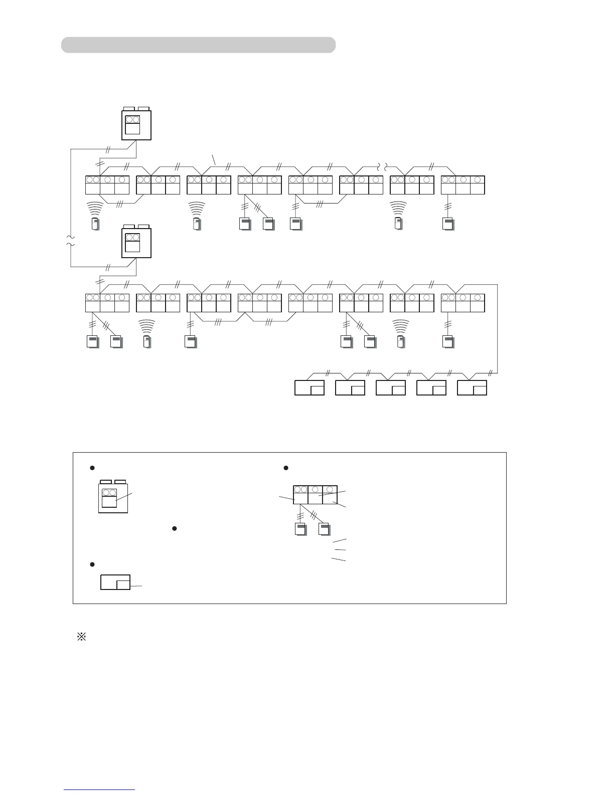
Instructions for setting up the address
1 The Refrigerant circuit address of the indoor and outdoor units can be set to optional
numbers in the range of 0 to 99.
2 The Indoor unit address can be set to optional numbers in the range of 0 to 15.
3 Set the Remote controller address in the order of 0,1,2,...15.(Blank is impossible)
4 The Central remote controller address can be set to optional numbers in the range of
0 to 15.
00
Central remote controller address
6
63 0
Indoor unit address
Remote controller address
63
Refrigerant
circuit address
Remote controller switch1
Number of indoor unit connection
Remote controller switch2
DSW1-1
DSW1-2
DSW1-4
OFF
OFF
OFF
ON
OFF
ON
Outdoor unit
Central remote controller
Indoor unit
Remote controller
Rotary-SW9,8
9 8
Refrigerant
circuit address
Rotary-SW9,8
9 8
6
10
Rotary-SW6
Rotary-SW10
0
1
2
3
4
5
0 0
14
0 15 0
0
63 0 163 0
2
63 0
3
63 1
4
63 2
5
63 0 6363
6
0
7
0
00 01 02 03 04
Transmission line
(Non-polar 2 core)
(Max.16)
2 Indoor units
2 Remote controllers
3 Indoor units
Central remote controller (Max.16)
63
9 8
0
9 8
9 8
6
10 9 8
6
10 9 8
6
10 9 8
6
10 9 8 6 10 9 8 6 10 9 8
6
10 9 8
6
10
9 8
6
10 9 8
6
10 9 8
6
10 9 8
6
10 9 8 6 10 9 8
6
10 9 8
6
10 9 8
6
10
0 0 0 0 0 00 1 0 0 0 1
DSW1-1
DSW1-2
DSW1-4
DSW1-1
DSW1-2
DSW1-4
DSW1-1
DSW1-2
DSW1-4
ON
ON
OFF
ON
OFF
OFF
ON
ON
OFF
ON
OFF
ON
OFF
OFF
OFF
1) For compact wall mounted type indoor unit, refer to 6-2-2.
1)
The following examples apply to all indoor units except for compact wall mounted type
indoor unit.
6-2-3 EXAMPLES OF SYSTEM SETTING
06-05