06-13
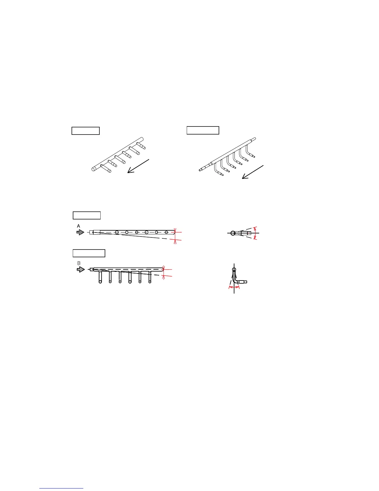
(1) Connection pipe to each indoor unit shall be connected from the edge of header.
(Connect the pipe in order of 1, 2, 3, ..... as shown in the figure below.)
Gas pipe Liquid pipe
1
2
3
1
2
3
(2) Header shall be mounted horizontally.
Permissible tolerance is 10mm (1
o
) between inlet and edge of the header.
(Always check with a level so that the header shall be positioned as shown below.)
0 to 10mm
(0 to 1
o
)
0 to 10mm
(0 to 1
o
)
Liquid pipe
Viewed from AViewed from A
-10 to 10
o
-10 to 10
o
Viewed from B
(3) Take a level
After the pipe welding and insulation, use a level again to make sure that the header
is positioned as shown in the figure above, and then secure it in place.
Gas pipe
7. Precautions on Header installation
Since necessary performance may not be obtained due to the mounting angle,
header installation is specified as follows.
8. Other installation information
Please refer to ( DESIGN & TECHNICAL DATA) to find more detailed installation
information on installation the outdoor unit, on installation space, on electrical wiring
and drain processing.