02-07
(Switch)
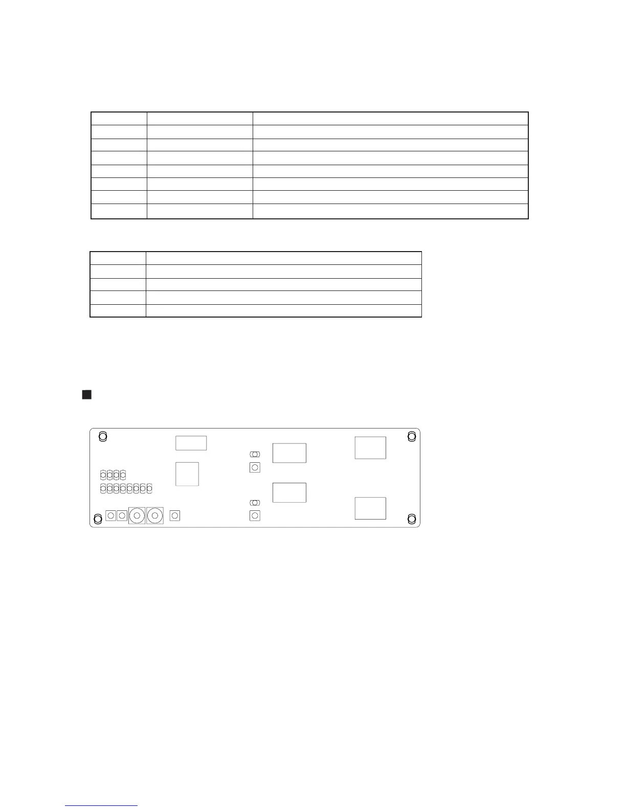
SWITCH AND LED POSITION
(2) NETWORK CONVERTOR (UTR-YLLA)
Switch No.
SW1
SW2
SW3
SW4
SW5
SW6
SW7
Push switch
Push switch
Push switch
Push switch
Rotaly switch (0-15)
Rotaly switch (0-15)
Push switch
CPU Reset
Selection of setting mode
Contents
(LED)
LED No.
D9
D14
D25-D18
D29-D26
Contents
Type
Service Pin SW (VRF side)
Service Pin SW (Lon works side)
Confirmation of setting
Setting up the value at the each setting mode (D25-D22)
Setting up the value at the each setting mode (D21-D18)
Light up when SW1 is pressed (Neuron ID Transmission)
Light up when SW2 is pressed (Neuron ID Transmission)
Indicates the setting mode selected with SW3
Indicates the setting value specified with SW5 and SW6
SW3
SW4
SW5
SW6
SW7
SW1
SW2
D9
D14
D29,28,27,26(From left)
D25,24,23,22,21,20,19,18(From left)