Connectable indoor unit capacity type2. 4. 1.
CAUTION
The total capacity of the indoor units connected must be between 27,000 and 39,000
BTU.
Connection patterns are restricted. Normal operatio n is not guaranteed if connected
pattern in the combination not listed below. The product may be damaged. Surely
connect in accordance with the combination in the following connection pattern.
To install an indoor unit, refer to the installation instruction sheet included with the •
indoor unit.
Indoor unit connection pattern
Indoor unit
1 2 3 4
1 18,000*
1)
18,000*
1)
– –
2 9,000 9,000 9,000 –
3 12,000 9,000 9,000 –
4 12,000 12,000 7,000 –
5 12,000 12,000 7,000 –
6 12,000 12,000 9,000 –
7 12,000 12,000 12,000 –
8 18,000 7,000 7,000 –
9 18,000 9,000 7,000 –
10 18,000 9,000 9,000 –
11 18,000 12,000 7,000 –
12 18,000 12,000 9,000 –
13 24,000 7,000 7,000 –
14 7,000 7,000 7,000 7,000
15 9,000 7,000 7,000 7,000
16 9,000 9,000 7,000 7,000
17 9,000 9,000 9,000 7,000
18 9,000 9,000 9,000 9,000
19 12,000 7,000 7,000 7,000
20 12,000 9,000 7,000 7,000
21 12,000 9,000 9,000 7,000
22 12,000 12,000 7,000 7,000
23 18,000*
2)
7,000 7,000 7,000
*1) An optional kit is required for the “18+18” combination. For more information, contact
your local dealer.
*2) ARU18RLF and AUU18RLF only. Wall mounted ASU18RLF cannot be connected in
this combination.
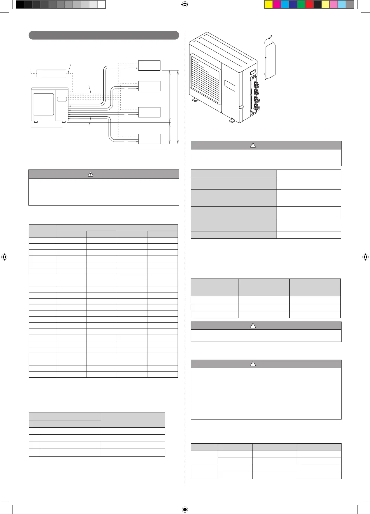
Outdoor port
Connectable model name
Standard port size
[mm (in.)]
D 6.35 (1/4) / 9.52 (3/8) 7 – 12
C 6.35 (1/4) / 9.52 (3/8) 7 – 12
B 6.35 (1/4) / 9.52 (3/8) 7 – 12
A 6.35 (1/4) / 12.7 (1/2)
7 – 12*
1
/18/24*
2
*1,*2 When connecting models 7–12 to the outdoor unit, the included adapter is neces-
sary. (For more information, refer to “4.1.3. How to use adapter”.)
UNIT D ø6.35mm, ø9.52mm (ø1/4 in., ø3/8 in.)
UNIT C ø6.35mm, ø9.52mm (ø1/4 in., ø3/8 in.)
UNIT B ø6.35mm, ø9.52mm (ø1/4 in., ø3/8 in.)
UNIT A ø6.35mm, ø12.7mm (ø1/4 in., ø1/2 in.)
Limitation of refrigerant piping length2. 4. 2.
CAUTION
The total maximum pipe lengths and height difference of this product are shown in the
table.
If the units are further apart than this, correct operation cannot be guaranteed.
Total max. length (a+b+c+d)
70 m (230 ft)*
1)
Max. length for each indoor unit
(a, b , c or d)
25 m (82 ft)
Max. height difference between
outdoor unit and each indoor unit
(H1)
15 m (49 ft)
Max. height difference between
indoor units (H2)
10 m (33 ft)
Min. length for each indoor unit
(a, b , c or d)
5 m (16 ft)
Total min. length (a+b+c+d)
20 m (66 ft)
)
*1) If the total piping is longer than 50 m (164 ft), additional refrigerant charging is neces-
sary. (For more information, refer to “6.2. Additional charging”.)
Selecting pipe sizes2. 4. 3.
The diameters of the connection pipes differ according to the capacity of the indoor unit.
Refer to the following table for the proper diameters of the connection pipes between the
indoor and outdoor units.
Capacity of indoor
unit
Gas pipe size
(thickness)
[mm (in.)]
Liquid pipe size
(thickness)
[mm (in.)]
7 – 12 ø9.52 (0.8) (3/8 (1/32)) ø6.35 (0.8) (1/4 (1/32))
18 ø12.7 (0.8) (1/2 (1/32)) ø6.35 (0.8) (1/4 (1/32))
24 ø15.88 (1.0) (5/8 (5/128)) ø6.35 (0.8) (1/4 (1/32))
CAUTION
Operation cannot be guaranteed if the correct combination of pipes, valves, etc., is not
used to connect the indoor and outdoor units.
Heat insulation around connection pipes requirements2. 4. 4.
CAUTION
Install heat insulation around both the gas and liquid pipes.
Failure to do so may cause water leaks.
Use heat insulation with heat resistance above 248 °F. (Reverse cycle model only)
In addition, if the humidity level at the installation location of the refrigerant piping is
expected to exceed 70%, install heat insulation around the refrigerant piping. If the
expected humidity level is 70-80%, use heat insulation that is 19/32 in. or thicker and if
the expected humidity exceeds 80%, use heat insulation that is 25/32 in. or thicker.
If heat insulation is used that is not as thick as specied, condensation may form on
the surface of the insulation. In addition, use heat insulation with heat conductivity of
0.045 W/(m·K) or less (at 68 °F).
Connect the connection pipes according to “4.1. Flare connection” in this installation
manual.
Operating range2. 4. 5.
Temperature Indoor air intake Outdoor air intake
Cooling
Maximum 90 °F DB 115 °F DB
Minimum 65 °F DB 32 °F DB
Heating
Maximum 88 °F DB 75 °F DB
Minimum 60 °F DB 14 °F DB
Indoor humidity about 80% or less
 Loading...