The electrical installation must be conducted in
accordance with the prevailing regulations.
The electrical connections must only be made when all
the other tting operations have been completed (xing,
assembly, etc.).
The heat pump must be supplied with power by
special protected leads from the electric panel
via 2-pole circuit breakers specially dedicated to the
heat pump : Curve D.
The electrical installation must necessarily be equipped
with a 30mA differential protection.
- Ensure that the general electrical power supply has
been cut off before starting any repair work.
- It is essential to maintain the live-neutral polarity when
making the electrical connections.
- Tighten the cables using the cable glands to prevent
the conductors from disconnecting accidentally.
- Ensure that the ground wire is longer to prevent
accidental disconnections.
"
• Connecting to regulation cards
- Remove the corresponding connector and make the
connection.
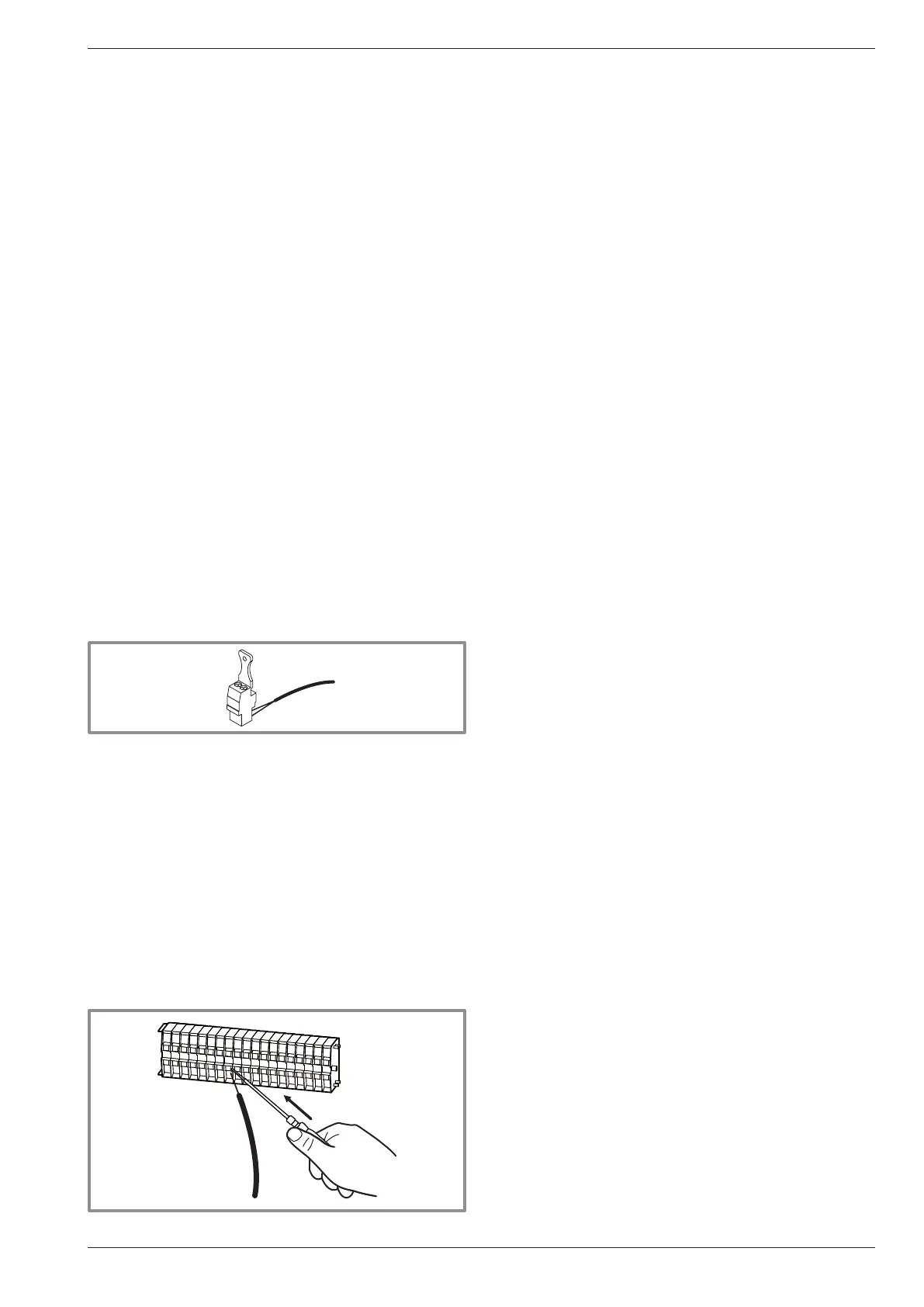
• Connecting to spring terminals :
Rigid wires
- Strip away around 10 mm from the end of the wire.
- Slide the wire into the opening provided for this
purpose.
- Push the spring with a screwdriver so that the wire
enters the cage.
- Remove the screwdriver and then check that the wire
is jammed in the cage by pulling on it.
Flexible wires
- Use the ends and proceed as before.
• Make the connections in accordance with the
diagram gure 7.
- Connect the interconnection cable between
terminals 1, 2, 3 and 4 (earth) of the control box and
the terminals 1, 2, 3 and earth of the heat pump.
• DHW tank with electrical back-up heating (option)
- Connect the distribution valve to connector
QX4, eath and N.
- Connect the domestic water sensor to terminal
BX1 and M.
- Conect the DHW back-up to terminals 17 (earth),
18 and 19.
- Connect the back-up electrical supply to terminals
14, 15 and 16 (earth).
- Connect the distribution valve (deviation boiler)
to the termianls 11 (earth), 12 and 13.
- Connect the boiler supply to terminals
8, 9 and 10 (earth).
• Floor heating system
Heated oor thermal safety fuse.
- The installer is responsible for connecting the heated
oor’s safety system. Thermal safety will stop the
heat pump if the temperature in the oor is too high.
The heated oor's safety system must cut the electrical
supply of the heat pump with a relay.
• Contract with the power provider :
The heat pump’s operation can be controlled to suit
special contracts (e.g. off-peak, day/night).
In particular, domestic hot water (DHW) at Nominal
temperature will be produced during the off-peak hours
when electricity is cheaper.
- Connect the "Power Provider” contact to input EX5.
- Set the parameter (1620) to "Off-peak hours".
• 230V on input EX5 = "Peak hours" information activated
(Basic setting / Modication possible line 5989,
menu Conguration).
• Power limitation or EJP (peak day removal) :
Power limitation is intended to reduce electrical
consumption when this is too high compared to the
contract with the power provider.
- Connect the power limiting device to input EX4, the
back-ups for the heat pump and the DHW stop in the
event of over-consumption by the dwelling.
• 230 V on input EX4 = power limitation in progress.
(Basic setting / Modication possible line 5987,
menu Conguration). (Operating line 2920)
• External faults the heat pump :
Any component of carryforward of information
(thermostat, pressure switch, etc.) may signal an
external problem and stop the heat pump.
- Connect the external component to input EX6.
• 230 V on input EX6 = stoppage of heat pump
(the system displays Error 369).
Installation and operating manual "1395 - EN" - 9 -
Control Box