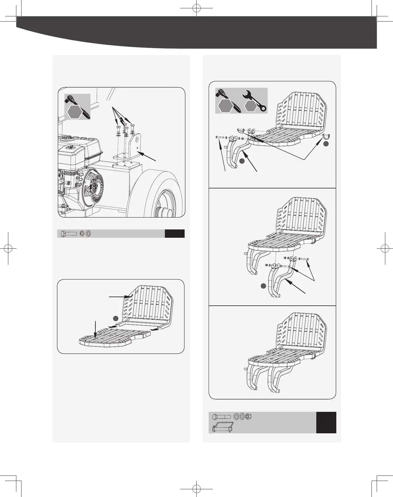
Connecting Plate Assembly
M10 x 20 x 4
5
Main Table & Side Table Assembly
1. Assemble the side table and the main table together to ensure that
the hole positions at the connection are aligned. (See Figure 20a,
illustration 1.)
2. Use a D type pin to insert the right connection hole between the
main table and the side table. (See Figure 20b, illustration 2.)
3. Align the front hole of the left support leg with the left connecting
hole between the main table and the side table, and x them with a
D type pin. At the same time, align the rear hole of the left leg with
the left hole at the bottom of the main table and then fasten with
M10x70 long bolts, washers and nuts. (See Figure 20b, illustration
3.)
Left Support Leg
M10x70 (x1)
Right Support Leg
Main Table
Side Table
D type pin 10x60 (x2)
M10x70 (x2)
4
3
2
1
Figure 19
Figure 20a
Connecting Plate
M10x20 (x4)
1. Assemble the connecting plate onto the tank, taking care to ensure
the correct bending direction of the plate. (See Figure 19.)
16 mm
4. Assemble the right support leg with the main table. Tighten with
bolts, washers and nuts. (See Figure 20b, illustration 4.)
M10 x 70 x 3
6
10 x 60 x 2
Left Support Leg
M10x70 (x1)
Right Support Leg
Main Table
Side Table
D type pin 10x60 (x2)
M10x70 (x2)
4
3
2
1
16 mm
13 mm
10 mm
24 mm
18 mm
19 mm
17 mm
Figure 20b
23
|
Assembly
 Loading...