F13 - Evaporator temperature (S2) for end defrost
F14 - Maximum duration of defrost (for security)
If the temperature in the evaporator (sensor S2) reaches the adjusted value, the end of defrost will be for
temperature. With this, the defrost process is optimized.
This function serves to adjust the maximum value of time for defrost. If evaporator temperature does not
reach the configured value in F13 in this period a point will blink in the right down side of display
indicating that end of defrost ocurred for time and not for temperature.
The end of defrost by time (which is not desired) can happen on the following situations:
-Adjusted temperature too high;
- Maximum time of defrost too short;
- Detached S1 sensor or without contact with evaporator.
Example:
(F13)
(F14)
F15 - Fan turned on during defrost
F16 - Defrost type
It makes possible the fan functioning during defrost.
Natural defrost or by resistances installed outside the evaporator.
"0" = Electrical defrost (resistances), where the defrost output is active.
"1" = Defrost by hot gas, where compressor and defrost outputs are actives.
F17 - Locked temperature indication (S1) during defrost
F18 - Draining time (dripping of defrost water)
F19 - Evaporator temperature (S2) for fan return after draining (fan-delay)
F20 - Maximum time of fan return after draining (fan-delay)
F19
This function prevents that room temperature elevation during defrost be visualized, keeping the last
indication before defrost. The indication is released again in the initial of refrigeration cycle, after fan-
delay.
Necessary time for dripping, it means, for draining the last water drops of evaporator.All the outputs are
kept off. If this stage will not be desired, adjust this time for “zero”.
The fan-delay cycle starts after draining. The refrigeration output (REF1) is active, therefore the ambient
temperature is high, but the fan is actived only after the temperature in evaporator is less than the
adjusted value. This process is necessary to remove the heat that still exists in the evaporator because
of defrost, preventing to transfer this heat to the ambient.
For security, if the temperature in the evaporator does not reach the adjusted value in or sensor S2
is detached, the fan-delay will happen on the adjusted time in this function.
F21 - Fan on with compressor off
F22 - Fan stopped for high temperature in evaporator
F23 - Offset indication forambient sensor (OffsetS1)
F24 - Offset indication forevaporator sensor (OffsetS2)
F25 Pre-defrosting time
During the refrigeration cycle, the fan activation may depends on the compressor status.
"0" = The fan is actived only while the compressor is active. This alternative, in some
cases, allows great economy of electric energy.
“1" = The fan is kept on during all refrigeration cycle.
It has for purpose the cycle of evaporator ventilation until the ambient temperature approaches the
desired temperature in the refrigerating installation project, preventing high temperatures and
pressures that can damage the compressor. If the temperature in evaporator exceed the adjusted value,
the fan is turned off and turned on again with a fixed hysteresis of 2°C below this value. Valuable
resource when refrigeration equipment that had been inactive for a few days or refrigerated cases are
restocked with its proper merchandise.
It allows to compensate eventual shuting lines on reading of ambient or evaporator sensor (S1 or S2),
proceeding of sensor exchange orcable length alteration.
This is to collect the remaining gas from the refrigerating gas line before starting the defrosting cycle, thus
increasing the system efficiency. Only the FANS output remains ON during thistime.
F26 - Max. operation timefor output REF1before maintenance.
F27 - Max. operation timefor output REF2before maintenance
This allows to configure an operation time (hours x 10) for output REF1 in order to indicate the need of
maintenance for the first compressor. When this operation time is reached, the display shows and
can be reset by theuser at thispoint.
This allows to configure an operation time (hours x 10) for output REF2 in order to indicate the need of
maintenance for the first compressor. When this operation time is reached, the display shows and
can be reset by theuser at thispoint.
5. OPERATION
5.1 - Parameters visualization
a)
b)
c)
d
e)
a) F01
b)
c) 5.1-b 5.1-c
d)
e)
Press at the same time and for 2 seconds until appear , releasing them after that.
Soon, appears .
Use and to access the desired function.
After selecting the function, press (short touch) to visualize the configured value.
) Press again (short touch) to return the functions menu.
To reset the menu and return to normal operation (temperature indication), press until appear
.
Access the function by pressing at the same time and for 2 seconds until appear ,
releasing then after that. Soon will appear , and then press (short touch).
Use and to enter the access code, and then press .
Select the desired function and visualize the configured value (see itens and ).
Use and to change the value and then press to record the configured value and return
to the functions menu.
To reset the menu and return to normal operation (temperature indication), press until appear
.
5.2 - Parameters configuration
SET
SET
SET
SET
SET
SET
SET
5.3 - Process stage, elapsed time, sensors S2 temperature
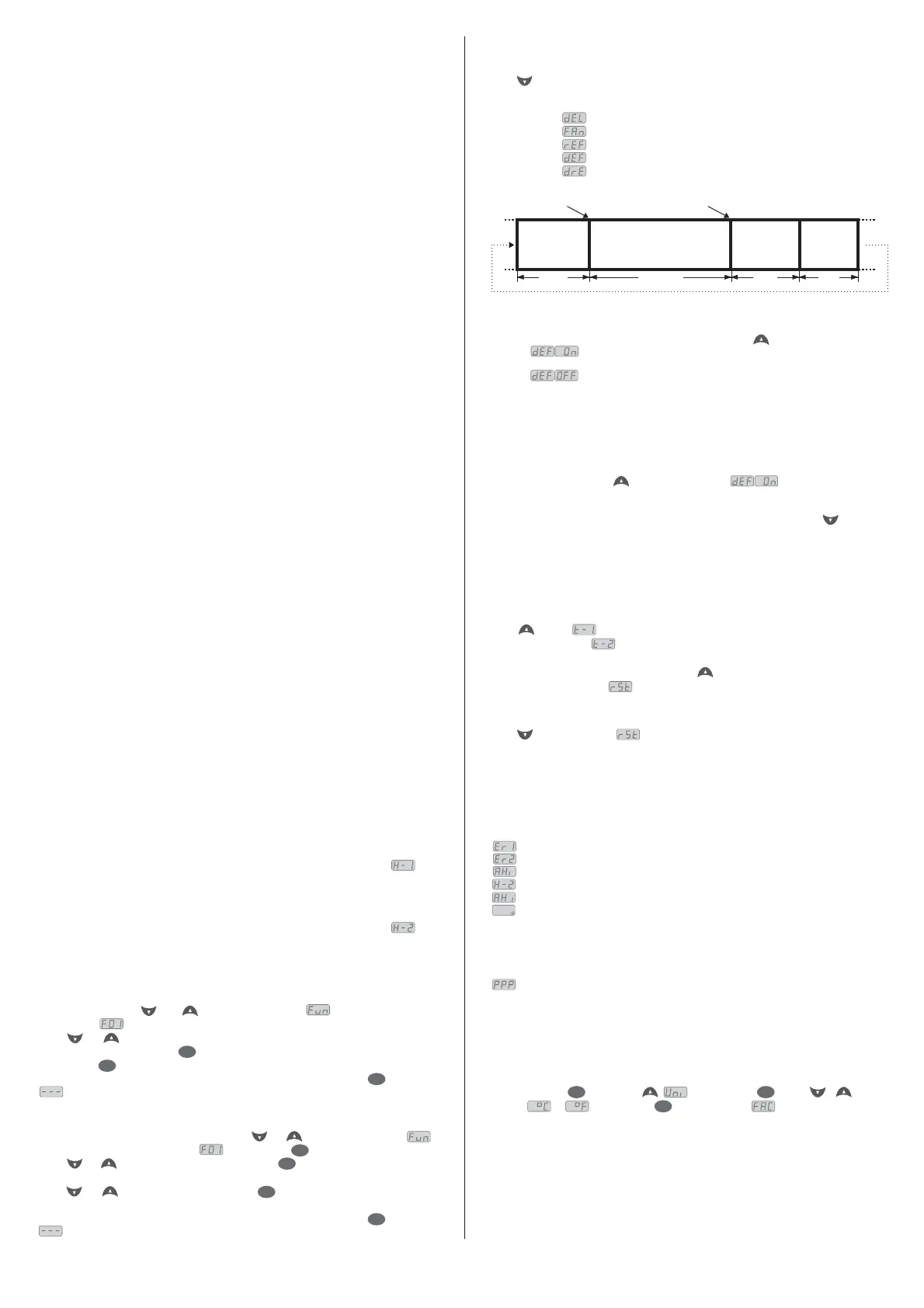
Press . The stage of the process will appear, the elapsed time (in minutes), the evaporator
temperature (sensor S2),
Process stages: Initial delay (delay to start the control)
Fan-delay (delay to fan return)
Refrigeration
Defrost
Draining
e
hourmeter time.
and the elapsed times of each hourmeter (in hours).
FAN-DELAY
REFRIGERATION
DEFROST
DRAINING
Indication released
F20 F14 F18F08
Indication locked (if enabled in F17)
5.4 - Manual defrost
To do a manual defrost, regardless of the programming, keep pressed for 4 seconds, until appears the
indication .
If the instrument is in defrost and you want to finish it, follow the above instructions, until appears the
indication .
5.5 - How to determine the end defrost by temperature
a)
b)
c)
d)
e)
f)
g)
h)
Adjust the follow functions with maximum values:
- Refrigeration time (F08 = 999 min)
- Evaporator temperature for end defrost (F13 = 75.0 ºC)
- Maximum duration of defrost (F14 = 90 min)
Waituntil an ice layer to be created on the evaporator
Do a manual defrost, pressing for 4 seconds, until appear .
Observe the melting process.
Wait until melt all icelayer on the evaporator toconsider the defrost finished.
Check the evaporator temperature read by the sensor S2 at this moment, pressing the key and copy this
value to the function F13 - Evaporator temperature (S2)for end defrost.
As security, adjust again the function F14 - that depends of the defrost type.
Now adjust the function F08 - with the desired value.
Maximum duration of defrost,
Exemple: Electrical defrost (resistance) =45 minutes as maximum
Defrost for by hot gas = 20 minutes as maximum
Refrigeration time,
5.6 - Minimum and maximum temperatures register
Press , soon appears and the minimum and maximum temperatures of S1 sensor (room
temperature). After soon appears and the minimum and maximum temperatures of S2 sensor
(evaporator).
Note: To reset the registers keep pressed the key during the visualization of the minimum and
maximum temperatures until to be showed.
5.7 - How to reset an alarmed hourmeter to zero
Press for 10 seconds until is displayed to reset any alarmed hourmeter to zero.
6 - INDICATORS AND ALARMS
The leds indicate the control outputs status:
: Compressor or solenoid of liquid gas;
: Compressor or solenoid of liquid gas;
: Evaporator fans;
: Defrost (heating);
REF
REF
FANS
DEFR
1
2
Room sensor S1disconnected or out of range;
Evaporator sensor S2 disconnected or out of range;
Alarm for output REF1 hourmeter;
7 - UNIT SELECTION (ºC / ºF)
To determine the unit that the instrument will work, access the function “F01” with the access cod 231 and
confirm with the key . Press the key . will appear. Press than use or to choose
between or and confirm with .After select the unit will appear and the instrument
returns to the function “F01”. Every time that the unit is changed, the parameters must be configurated again,
because they assume the standard values.
SET SET
SET
Alarm for output REF2 hourmeter
Sensor 1high temperature alarm;
Always that defrost ends for time and not for temperaure, a point located in the right down side of
display will blink until the next defrost indicating that:
- The interval between defrosts is too high;
- There are burned resistances;
- There is an inoperative fan or the adjusted time is too short for the maximum duration of defrost.
Invalid configuration parameters
- In this situation the outputs are turned off;
- Check which parameters have invalid data and correct them to return to normal operation.
- The hot gas is not circulating;
;

 Loading...