CONTROLLER
10. DISPLAY SIGNALINGS
Room sensor error: Sensor disconnected or damaged.
[Err1]
[Err2]
[Athi]
[atlo]
[alrC]
[Open]
[OFF,]
[AOPN]
[ECal]
[pppp]
Contact Full Gauge Controls.
Evaporator sensor error: Sensor disconnected or damaged.
High room temperature alarm (sensor 1).
Low room temperature alarm (sensor 1).
Maximum compressor on time exceeded without reaching the control
temperature (setpoint).
Door open indication.
Indicates drainage in progress.
Control routines turned off.
Open door alarm.
11. GLOSSARY OF ACRONYMS
- °C: Temperature in Celsius degrees.
- °F: Temperature in Fahrenheit degrees.
- Defr: Defrost.
- LOC: Blocked.
- No: No.
- OFF: Turned off/disabled.
- ON: Turned on, enabled.
- Refr: Refrigeration.
- SET (as in "Setting") (setting or configuration).
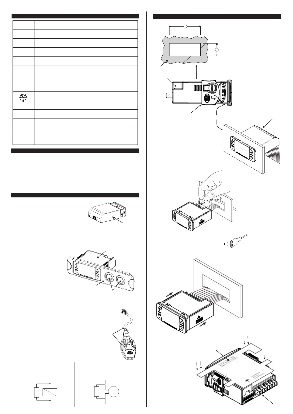
12. OPTIONAL ITEMS - Sold Separately
ECASE PROTECTIVE CASE
Extended frame
It allows the installation of Evolution line controllers with sizes 76 x 34 x 77 mm in various situations,
since it does not require precision in the notch of the instrument fitting panel.
The frame integrates two switches of 10 Amperes that may be used to actuate interior light, air curtain,
fan, and others.
- version 2 or higherEasyProg
It is an accessory that has as its main function to store the parameters of the controllers. At any time, you
can load new parameters of a controller and unload them on a production line (of the same controller),
for example. It has three types of connections to load or unload the parameters:
- Serial RS-485: It connects via RS-485 network to the controller (only
for controllers that have RS-485).
- USB: it can be connected to the computer via the USB port, using
Sitrad's Recipe Editor.
- Serial TTL: The controller can be connected directly to EasyProg
by the TTL Serial connection.
CONTROLLER
EXTENDED
FRAME
SWITCHES
EASYPROG
Led flashing
Reconfigure the function values.
Alert of defrost concluded by time and not by temperature. The dot
in the lower right corner of the display will blink until the next defrost
(if enabled by the function [,f72]).
[,,,,*]
Surge Protective
Wiring diagram for instalation of SPD
in magnectic contactor
A1 and A2 are the terminals of the
contactor coil.
A1
A2
SPD
Wiring diagram for instalation of SPD in
line with loads
For direct drive take in to consideration the specified
maximum current.
Load
SPD
Ecase protective cover
It is recommended for the Evolution line, keeps water from
entering the back part of the instrument. It also protects the
product when the installation site is washed.
NOTE: Ecase is compatible with the use of small type
Faston terminals, usually with silicone protection.
Image VI
Image VII
PANEL
LATCHES
CONTROLLER
CONTROLLER
13. ANNEXES - Reference Images
Image V
Y
X
PANEL
Image VIII
Image IX
VINYL
For correct and safe installation,
make all connections before
securing the controller.
IMPORTANT:
Faston connectors should be
protected with covers, preferably
silicone.
 Loading...