6.4. NBR5410 and IEC60364 standard recommendations
a) Install voltage overload protection in the power supply line of the controller.
b) Install surge protectors-suppressor filter (RC type) - in the circuit to improves instruments
performance. See instructions on how to connect the filter on the previous page.
c) Sensor cables may run together, but not through the same mains where the electricity supplies of the
controller and / or loads pass.
7. FASTENING PROCEDURE
a) Cut out sheet metal of the panel (image V - item 15) where the controller will be fastened, with the
dimensions X = 71 ± 0.5 mm and Y = 29 ± 0.5 mm;
b) Remove the side locks (image VII - item 15): to do that, press the central elliptical part (with Full
Gauge Controls Logo) and move the latches backwards;
c) Insert the controller in the notch made on the panel, inwords;
d) Place the locks and move them until they are pressed against the panel, fastening the controller into
the housing (see the indication of the arrow on image VII - item 15);
e) Perform the electric installation as described in item 6;
f) Adjust the parameters as described in item 8.
WARNING: for installations that require liquid tightness, the opening to install the controller
must be 70.5 x 29 mm maximum. The side locks must be fixed in order to press the sealing
gasket to prevent infiltration between the opening and the controller.
Vinyl protection - Image VIII (item 15)
It protects the controller when it is installed in locations subjected to splashes of water, such as
refrigerated display counters.
This vinyl protection is included with the instrument.
IMPORTANT: Apply only after finishing the electric connections.
a) Push the side locks backward (Image VII - item 15);
b) Remove the protective film from the adhesive face of the vinyl;
c) Apply the vinyl on the entire upper part, bending the tabs as indicated by the arrows - image VIII (item
15);
d) Reattach the locks.
NOTE: The vinyl is transparent, allowing the instrument's electric diagram to be seen.
8. AD JUS TI NG TH E D ESIRE D T EM PE RATU RE AND
PARAMETERS
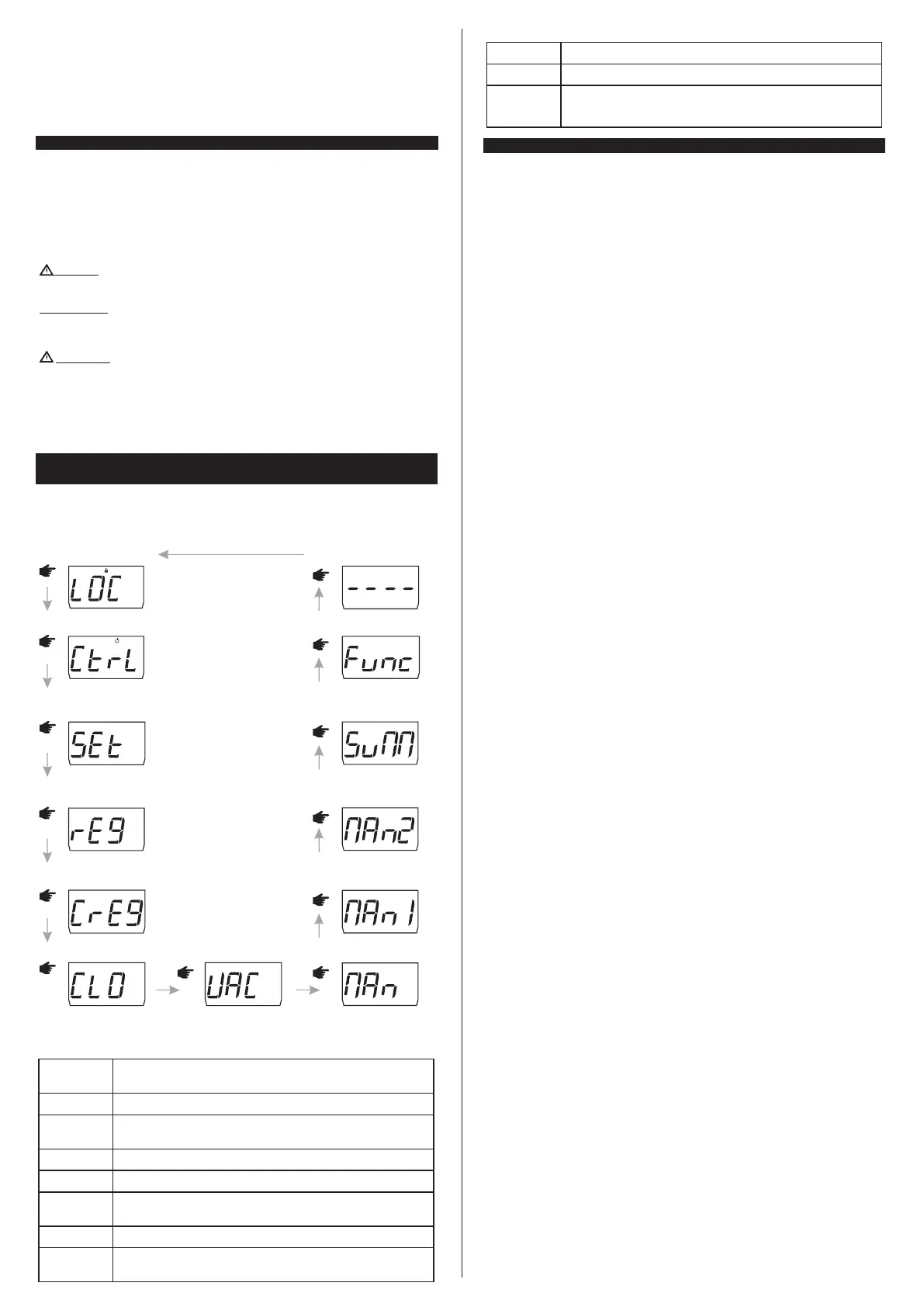
8.1. Quick Access Menu Chart
To access or browse the quick access menu, use the ;key (quick touch) while the temperature is being
displayed by the controller. With each touch the next function in the list is displayed. To confirm use the ;
key (quick touch). For more details, see chapter 8.3; below is the map of functions:
;
FUNCTIONS LOCK
;
CONTROL FUNCTIONS SHUTDOWN
EXIT FUNCTION
;
FUNCTION SELECTION
;
ERASE MIN. AND MAX. VALUES
;
MIN. AND MAX. TEMPERATURE
RECORD
;
Microsol II e plus
Microsol II e plus
Microsol II e plus
Microsol II e plus
Microsol II e plus
Microsol II e plus
SWITCH BETWEEN MANUAL
AND AUTOMATIC MODE
;
Microsol II e plus
SETPOINT ADJUSTMENT
(SP1, SP2, AND HT2)
;
Microsol II e plus
DATE AND TIME VIEW
;
Microsol II e plus
ACTIVATE / DEACTIVATE THE
VACATION FUNCTION
;
Microsol II e plus
BACKUP 1 SWITCH BETWEEN
MANUAL AND AUTOMATIC
MODE
;
Microsol II e plus
BACKUP 2 SWITCH BETWEEN
MANUAL AND AUTOMATIC
MODE
;
Microsol II e plus
MANUALLY INCREASE /
DECREASE THE TIME FOR
DAYLIGHT SAVINGS TIME
;
Microsol II e plus
8.2. Quick access keys map
When controller is on temperature display mode, the following keys can be used as a shortcut for the
following functions:
Quick touch: the current day, month, year, day of the week, hour, and
minute/temperature will be shown in sequence on the display.
Held down simultaneously: access to the function selection.
/
<
<
Held down for 5 seconds: switch between manual and automatic pump
activation mode.
/
Held down for 5 seconds: backup 2 switch between manual and
automatic activation mode.
<
Quick touch: enter the quick access menu.
;
Held down for 5 seconds: control functions shutdown.
;
/
Held down for 2 seconds: Setpoint adjustments (SP1, SP2, AND HT2).
Quick touch: display of the maximum and minimum measurements recorded.
<
<
Held down for 2 seconds: clear history when records are being displayed.
Quick touch: momentarily switches the temperature view.
<
Held down for 5 seconds: backup 1 switch between manual and
automatic activation mode.
<
9. BASIC OPERATIONS
9.1 Backup operating temperature adjustment (SETPOINTS)
Pressing/for 2 seconds you can adjust the operating temperature of Backup 1 and Backup 2, as well
as the superheating temperature of sensor 2 (tank / swimming pool). The message [Sp1,], will be
displayed; adjust the operating temperature of Backup 1 using the <or>key, press/to confirm.
Then the message [Sp2,], will be displayed; adjust the operating temperature of Backup 2 as
described above. After pressing the /key the message [Ht2,] will be displayed for the adjustment
of the superheating temperature of sensor 2. Again, use the <or> keys to change the value and
press/to confirm. Finally the indication [----] is signaled concluding the configuration. The
setpoints may also be adjusted in the quick access menu.
9.2 Viewing other temperatures
To switch between the temperature views for sensor 1, sensor 2, sensor 3 (if enabled) and temperature
difference, press > until the desired temperature is displayed.
[T-1,] Sensor 1 temperature
[T-2,] Sensor 2 temperature
[T-3,] Sensor 2 temperature
[dif,] Temperature differential (T1-T2)
The selected temperature will be displayed for 15 seconds and then the default indication will return (as
per [,F01]parameter setting).
9.3 Minimum and maximum temperature record
By pressing the < key or also through the quick access menu (see item 6), the message [rEg,] will
be displayed and then message [t-1,] indicating the temperature of sensor 1 and the maximum and
minimum recorded temperatures immediately after, then the temperature of sensor 2 [t-2,], sensor
3 [t-3,](if enabled), and differential [DiF,]. will be displayed. To erase the current minimum and
maximum values, press the ; key (quick touch) until the message [CrEg] is displayed. Press /to
confirm.
Note: If the <key is pressed while the records are being displayed the values will be reset and the
message [rst,] will be displayed.
9.4 View current date and time
Quickly pressing the/key makes possible to view the current date and time set in the controller. The
display will show sequentially the current day ([,--d]), mouth ([,--m]), year ([,--y]), weekday
([day-]) hour and minute ([00:00]) and if the preferred view set in [,F01] or[Hour], the
temperature is also displayed. It is also possible to view the date and time through the quick access
menu in the option[ClO,].
9.5 Manual pump activation
The pump is manually activated by pressing the / key for 5 seconds.
When the manual mode is selected, the pump remains on for 6 hours (fixed time) and then the controller
assumes the automatic mode. If you want to return to the automatic mode before the 6 hours have
elapsed, press the / key again for 5 seconds to deactivate the manual mode; the message [AUTo]
will be displayed.
The message [Man,] is displayed upon manual activation, this message alternates with the display of
the default indication [,F01]. It is also possible to choose the mode through the quick access menu
[man,].
NOTE: It is not possible to activate the manual pump mode when the control shutdown is active.
NOTE : Manual pump mode can be activated even with one or more sensor errors.
9.6 Manual activation of backup 1
Backup 1 is manually activated by holding the > key down for 5 seconds.
When the manual mode is selected, backup 1 keeps regulating the temperature regardless of the event
schedule for the time defined in [,F20], after the controller assumes automatic mode. If you want to
return to the automatic mode before this time has elapsed, hold the > key down again for 5 seconds to
deactivate the manual mode; the message [AUTo]will be displayed.
The message [Man1]is displayed upon manual activation, this message alternates with the display of
the default indication [,F01]. It is also possible to choose the mode through the quick access
menu[man1].
9.7 Manual activation of backup 2
The backup 2 is manually activated by pressing the < key for 5 seconds.
When the manual mode is selected, backup 2 keeps regulating the temperature regardless of the event
schedule for the time defined in [,F26], after the controller assumes automatic mode. If you want to
return to the automatic mode before this time has elapsed, hold the < key down again for 5 seconds to
deactivate the manual mode; the message [AUTo]will be displayed.
The message [Man2]is displayed upon manual activation, this message alternates with the display of
the default indication [,F01].
It is also possible to choose the mode through the quick access menu[man2].
NOTE: If the controller's control functions are disabled or if vacation mode is enabled, manual activation
of the backups will not be allowed.
9.8 Vacation Mode
Vacation mode can be activated using the quick access menu (;), option [Vac,] and pressing/to
confirm.
When active:
* The event schedule is disregarded and the backup outputs are switched off, resulting in a reduction in
power consumption.
* Carries out the cooling of the tank as programmed in [,F30] - Temperature to switch off the cooling
in vacation mode (S3).
 Loading...