DIGITAL CONTROLLER FOR HEATING OR COOLING
WITH DEFROST AND CONFIGURABLE
ALARM OUTPUT
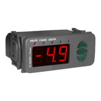
4. INDICATIONS AND KEYS
1. DESCRIPTION
The MT-514e FASTON is a temperature controller for applications in refrigeration or heating. It
has an internal buzzer and an alarm output can also be configured for electric defrost or hot gas. The
minimum and maximum is displayed at the touch of a single key (Flatec).
Another available feature is the shutdown of the control functions, making it possible for the
MT-514e FASTON only operate as a temperature gauge. And through a system functions,
prevents unauthorized persons from changing control.
Product conforming to UL Inc. (United States and Canada).
2. APPLICATION
• Vaccine refrigerators
• Refrigerated counters
• Freezer rooms
• Hot counters
• Greenhouses
evolution
MT-514e Faston
Ver
.02
FOR INSTALLATIONS WHERE A SEALING IS REQUIRED TO AVOID LIQUID CONTACT, THE CUT FOR THE
CONTROLLER MUST BE OF 70,5X29mm MAXIMUM. THE SIDE LOCKS MUST BE FIXED SO IT PRESSES THE
RUBBER SEALING AVOIDING INFILTRATION BETWEEN THE CUT AND THE CONTROLLER.
ATTENTION
WARNING
ACCESSORIES:
Only use original Full Gauge Controls accessories.
If you have any questions, please contact technical support.
AUTHORIZED SERVICE:
The installation or maintenance of the product must be performed by qualified professionals only;
(*) This instrument measures and controls temperatures of up to 200°C/392°F, using the silicone sensor cable SB59
(sold separately).
Note: The sensor cable lenght can be increased by the user up to 200 meters using PP 2 x 24 AWG cable.
3. TECHNICAL SPECIFICATIONS
Control temperature
-50 to 105ºC (-58 to 221°F)*
Power supply
MT-514 E Faston: 115 or 230 Vac ±10%(50/60 Hz)
MT-514 EL Faston: 12 or 24 Vac/dc +10%
Operating temperature
0 to 50 ºC / 32 to 122°F
Operating humidity
10 to 90%RH (without condensation)
Dimensions (mm)
76 x 34 x 84 mm (WxHxD)
Load current (outputs)
OUT1: 16(12)A 250Vac 2HP
OUT2: 10A / 240Vac 1/4HP
Dimensions of the clipping for fixing
of the instrument
71 ± 0,5 x 29 ± 0,5 mm (see item 5)
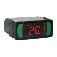
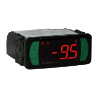
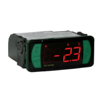
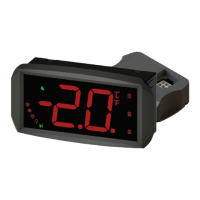
MT-514e
Set key
Quick Access
Menu Key (Flatec)
Functions lock indication LED
Temperature unit indication LED
Increase key
Decrease key
Alarm indication LED
Cooling indication LED
Heating indication LED
Defrost indication LED
DUE TO YOUR CONSTANT EVOLUTION, THE FULL GAUGE CONTROLS RESERVES THE RIGHT TO
CHANGE THE INFORMATION CONTAINED IN THIS MANUAL AT ANY TIME WITHOUT NOTICE.
BEFORE INSTALLING THE CONTROLLER, WE RECOMMEND READING THROUGH THE
ENTIRE INSTRUCTION MANUAL IN ORDER TO AVOID POSSIBLE DAMAGE TO THE
PRODUCT.
PRECAUTIONS WHEN INSTALLING THE PRODUCT:
Before performing any procedure on this instrument, disconnect it from the mains;
Ensure that the instrument has adequate ventilation and avoid installation in panels containing
devices that may cause it to operate outside the specified temperature limits;
Install the product away from sources that may generate electromagnetic disturbances such as:
motors, contactors, relays, solenoid valves, etc;
Have this manual in the palm of
your hand by FG Finder application.
6. WIRING DIAGRAM
6.1. Identifications (see Images I to IV)
- Image I: MT-512E 2HP Faston, supplied at 115 Vac.
- Image II: MT-512E 2HP Faston, supplied at 230 Vac.
- Image III: MT-512EL 2HP Faston, supplied at 12 Vac/dc.
- Image IV: MT-512EL 2HP Faston, supplied at 24 Vac/dc.
Image I
1
5
6
2
3
4
7
POWER
SUPPLY
SENSOR
8
9 10
11
12
13 14
REFR
115 Vac
Power supply
COMMON
D1
ALRM/
DEFR
COMMON
NO
NC
/
1
5
6
2
3
4
7
POWER
SUPPLY
SENSOR
8
9 10
11
12
13 14
REFR
230 Vac
Power supply
COMMON
D1
ALRM/
DEFR
COMMON
NO
NC
/
1
5
6
2
3
4
7
POWER
SUPPLY
SENSOR
8
9 10
11
12
13 14
REFR
12Vac/dc
Power supply
COMMON
D1
ALRM/
DEFR
COMMON
NO
NC
/
0
1
5
6
2
3
4
7
POWER
SUPPLY
SENSOR
8
9 10
11
12
13 14
REFR
24Vac/dc
Power supply
COMMON
D1
ALRM/
DEFR
COMMON
NO
NC
/
0
Image II
Image III
Image IV
6.1. Temperature sensor connection
- Connect the sensor S1 wires to terminals "1 and 2" and wires sensor S2 to terminals "3 and 4": the
polarity is not relevant.
- Length of the sensor cables can be increased by user himself to up to 200 meters, using a PP 2x24
AWG cable.
6.2. Recommendations of IEC60364 standard
a) Install overload protectors in the controller supply.
b) Install transient suppressors – suppressor filter RC – in the circuit to increase the service life of the
controller relay. See connection instructions of the filter on the previous page.
c) The sensor cables may be together, but not in the same conduit where the power supply of the
controller and/or of the loads passes through.
NEW CONNECTION SYSTEM (QUICK COUPLING):
FASTON and PUSH-IN FAST
CONNECTION:
- Hold the wire near its end and insert it into the
desired slot.
- If necessary, press the bottom to assist the
connection.
DISCONNECT:
- To disconnect the cord, press the bottom and
remove it.
NOTE:
- In the connectors 1 to 6 the maximum wire
diameter that can be used is 1,5mm².
- The wires must be tinned or use Rocket Pin
terminals with a maximum diameter of 0,75mm².
BOTTOM
WIRE INPUT
The wire should be picked
in 5 mm and tinned.
Terminal Rocket Pin.
7. FIXING PROCEDURE
a) Cutout the panel plate (Image V - item 13) where the controller will be fixed, with dimensions
X = 71±0,5 mm and Y = 29±0,5 mm;
b) Remove the side locks (Image VI - item 13): To do this, squeeze the elliptical central part (with the
Logo Full Gauge Controls) and move the latches back;
c) Pass the wires through the cutout of the plate (image VII - Item 13) and make the electrical installation
as described in item 6;
d) Insert the controller into the panel cutout, from the outside in;
e) Replace the latches and push then until they are pressed against the panel, securing the controller to
the housing (see arrow in Figure VI - item 13);
f) Adjust the parameters as described in item 9.
Control
functions
shutdown
Function
blocking
Serial
Programming
Defrost
Protection
level
IP 65
FRONT
Audible
Alarm
Connector
for quick
coupling
MT514EFASTONV02-03T-16721
MT-514e
MT-514
e
E251415