F31 - Output on time in OUT2 alarm status:
F32 - Output off time in OUT2 alarm status:
Selects the cycling time in seconds of the alarm output when it is active. If any of those functions are set
with a value of [,,,0] the output will be permanently active.
F33 - Open door time for alarm:
If the door remains open for a time equal to, or greater than, the one configured in this parameter, the
controller will set off a visual open door alarm [AOPn] and the audible alarm (Buzzer).
The alarms are suspended upon the door closing. The audible alarm may be inhibited through the >
key (pressed for 2s). This function can be switched off by setting it at the minimum value 0 [no,,].
Note 1: In order for the open door alarm to operate, the function “Digital input operating mode” [,F30]
must be configured as open door contact.
The audible alarm is activated only if the buzzer is enabled in the function “Enable Buzzer (0-Disabled
/1-Enabled)” [,F29].
Note 2: If the function “Digital input operating mode” [,F30] is configured as open door contact, the
open door indication [OPEn] will be displayed every time the door is open, except for the cases of
alarm.
F34 - Operating mode of the digital filter:
[,,,0]- The filter acts both on the rise as on the decrease temperature.
[,,,1]- The filter acts only in the temperature rise ramp. When the temperature falls, your response
will be immediate.
F35 - Digital filter intensity applied to the sensor:
This filter has the purpose of simulating increase in thermal mass at the sensor thereby increasing its
response time (thermal inertia). The higher the value set in this function, the more time the sensor takes
to respond.
This function can be switched off by setting it at the minimum value 0[no,,].
F36 - Functions lockdown:
This allows and configures the functions lockdown.
[,,,0]- Do not allow the functions lockdown.
[,,,1]- Allow a partial lockdown where the control functions will be locked but the adjustment of the
setpoint, manual defrost, and maximum and minimum record are allowed.
[,,,2]- Allow the full lockdown, enabling only the manual defrost and maximum and minimum
record.
F37 - Time for functions lockdown:
Allow lockdown of control functions (see item 6.3.3).
[,,15] - [,,60] Defines the time in seconds for the controller to activate.
F38 - Control functions shutdown:
Allow control functions shutdown (see item 6.3.4).
[no,,]Disables the control functions shutdown.
[,,,1]Enables activation/deactivation of the control functions only if the functions are unlocked.
[,,,2]Enables activation/deactivation of the control functions even if the functions are locked.
Control functions off.
Contact Full Gauge Controls.
Reconfigure the values of the functions.
[OFF,]
[eCAL]
[pppp]
7. SIGNALS
Sensor disconnected or damaged.
Manual activation of defrost process.
Manual activation of end of defrost process.
[Err1]
[Defr][On,,]
[defr][Off,]
Low temperature alarm.
[Atlo]
[inib]
[LOC,][On,,]
[LOC,][OFF,]
[AVoL]
[AOPn]
[OpEn]
Power outage alarm indication.
Open door alarm indication.
Open door indication.
Functions lockdown.
Unlocking of functions.
Buzzer inhibited.
Example of connections for detecting open door and power outage:
This configuration may be used to detect power outage alarm (115/230 V AC) and also to detect that the
door has been left open (either one event).
In those configurations, the messages [AVoL] and [AOPn]are displayed alternately when alarm
event is detected (power outage or open door alarm).
For this purpose, the user may use the pushbuttons (not supplied) and a contactor or auxiliary contact
(not supplied) connected in series or in parallel, as shown in examples below:
Examples of connection for power outage detection:
This configuration may be used when MT-514e Faston is being energized by a 12/24 V DC
battery (common in vaccine refrigerators) and one wants to detect when a power outage occurred
(115/230 V AC). In this configuration, the message[AVoL] is displayed when alarm is detected for
power outage. To that end, the user may utilize a contactor or auxiliary contact (not supplied), where NC
(F30=[,,,3]) or NO (F30=[,,,4]) contacts are connected to the digital input and contacts A1 and
A2 (contactor coil) are connected to the power system, as shown in examples below:
[Athi]
[ALrC]
High temperature alarm.
Compressor reached maximum time on limit without reaching SP.
F25 - High temperature alarm:
The temperature above which the instrument indicates high visual temperature alarm [Athi] and the
audible alarm (Buzzer). The differential for alarm shutdown is set at 0.1 °C/1 °F. This alarm considers
the temperature displayed, thus being influenced by the indication of temperature lockdown during
defrost [,F18].
Note: For safety reasons, output OUT1 is switched off when the controller is configured for heating and
a high temperature alarm [athi] occurs, or when it is configured for cooling and a low temperature alarm
[atlo] occurs. For this reason you must configure the alarm threshold above (if heating) or below (if
cooling) the desired temperature (setpoint of output OUT1).
F26 - OUT2 output operating mode:
Selects the OUT2 output operating mode:
[,,,1]- Absolute extra-range alarm: Considers the values defined in[,F24]and[,F25]as
minimum and maximum values to activate the alarm output.
[,,,2]- Extra-range alarm relating to the setpoint: Considers the active preset setpoint [rc1,]
or [rc2,] and the absolute values defined in [,F24] and [,F25], i.e. the positive value of these
functions as minimum and maximum values to activate the alarm output.
For example:
Desired temperature[SP,,]: - 5 °C
Low temperature alarm [,F24]: 2 °C
High temperature alarm [,F25]: 2°C
Limits: ([SP,,] - [,F24] and [SP,,]+ [,F25]).
The low temperature alarm will be signaled at -7°C(-5 -2) and the high temperature alarm at -3°C(-5+2).
[,,,3] - Electric defrost (by resistance): Where only the OUT2 output is activated during the
defrost process.
[,,,4] - Hot gas defrost: Where the OUT1 and OUT2 compressor outputs are activated during the
defrost process.
[,,,5] - OUT2 output as OUT1 output NC: In this option, the OUT2 output is activated when OUT1
output is deactivated, irrespectively of the state (cooling/heating or defrost), except when the sensor is
in error [,F20].
Note: If the OUT2 output is configured to work differently from alarm, the indications of absolute alarm
are still visual (messages in the display) and audible (if the buzzer is enabled).
Note 2: If the OUT2 output is configured to work as defrost (electrical or hot gas), after elapsing of
defrost time a fixed 2-minute time period is counted for drainage. This time is necessary for the dripping,
i.e. for the last drops of water to run from the evaporator. Within this period, outputs OUT1 and OUT2
remain off.
F27 - Alarm inhibition time when energizing the controller:
This is the time during which the alarm remains off even under conditions of alarm during the instrument
start-up. This time will be counted after elapsing of the time configured in [,F19]. This function can be
switched off by setting it at the minimum value 0 [no,,].
F28 - Alarm inhibition time by temperature:
With this configuration active, the temperature will need to remain in the alarm condition during the
inhibition time set, for the alarm to be indicated. That way one can prevent alerts resulting from specific
temperature variations, and after defrost.
F29 - Enable buzzer (0-Disabled/1-Enabled):
Allows enabling and disabling of the internal buzzer for alarm signaling.
F30 - Digital input operating mode:
Selects the digital input operating mode.
[no,,]- Disabled
[,,,1]- Digital input: Open door (active at the contact closing)
[,,,2]- Digital input: Open door (active at the contact opening)
[,,,3]- Digital input: External alarm/power outage (active at the contact closing)
[,,,4]- Digital input: External alarm/power outage (active at the contact opening)
[,,,5]- Digital input: Open door and power outage (active at the contact closing)
[,,,6]- Digital input: Open door and power outage (active at the contact opening)
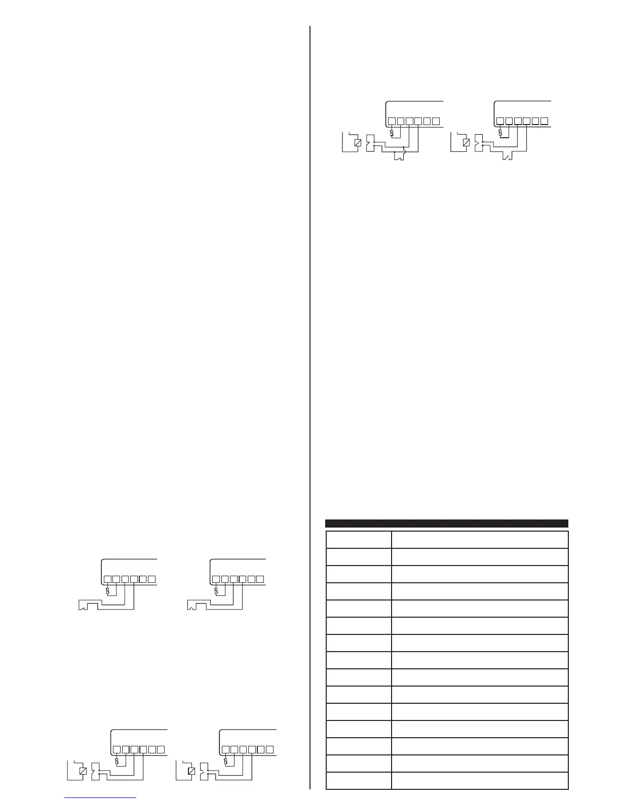
Examples of connection for detecting open door alarm:
This configuration may be used for the MT-514e Faston to detect whether the door has been left
open for a time above the value set up in “[,F33] - Time with open door to trigger alarm”. In this
configuration, the message [AOPn] is displayed when an open door alarm is detected. To that end, the
user may use the NO or NC pushbuttons (not supplied) connected to the digital input, as shown in
examples below:
F30 =[,,,1]
1
5
6
2
3
4
SENSOR
NC
Door contact
F30 =[,,,2]
1
5
6
2
3
4
SENSOR
NO
Door contact
F30 =[,,,3]
1
5
6
2
3
4
SENSOR
NC
NC
Vca
A1
A2
F30 =[,,,4]
1
5
6
2
3
4
SENSOR
NO
NO
Vca
A1
A2
F30 =[,,,6]
Serial connection
1
5
6
2
3
4
SENSOR
NO
NO
Vca
A1
A2
NO
Door contact
F30 =[,,,5]
Parallel connection
1
5
6
2
3
4
SENSOR
NC
NC
Vca
A1
A2
NC
Door contact
 Loading...