7-7
A8C70BLP
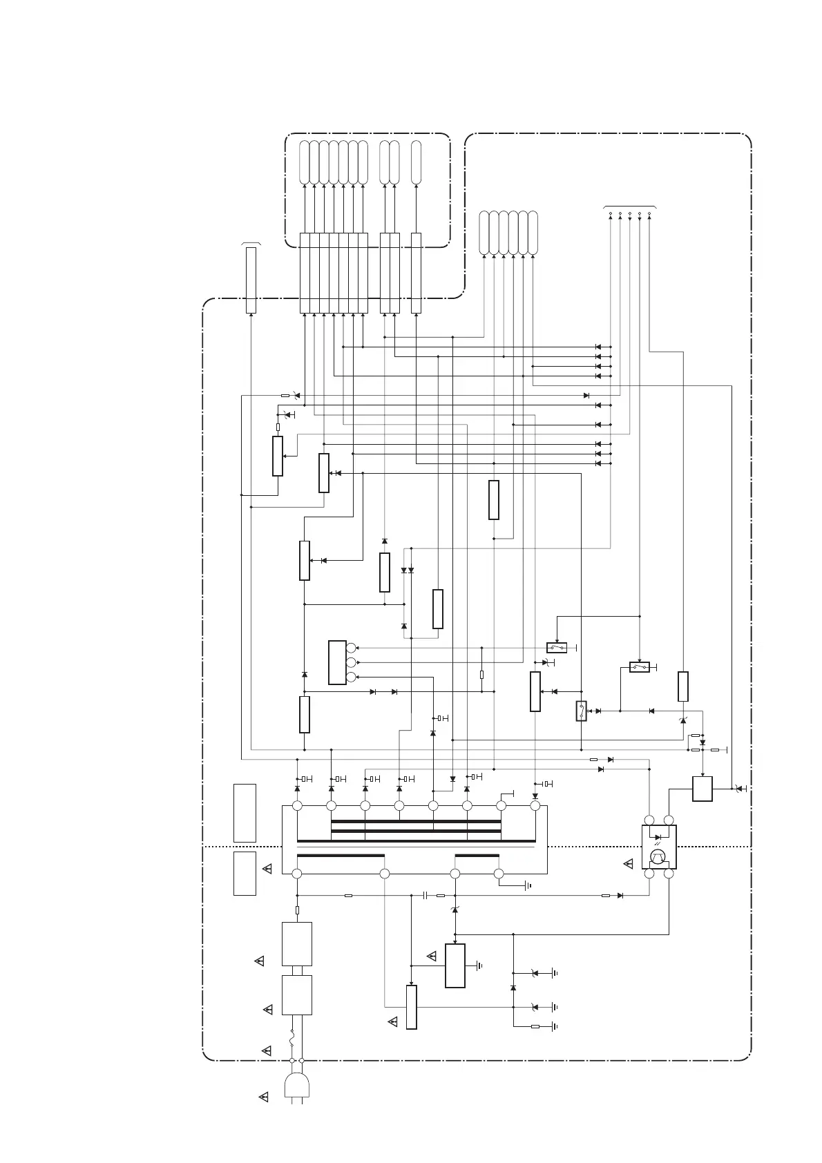
Power Supply Block Diagram
LINE
FILTER
L601
AC601
AC CORD
BRIDGE
RECTIFIER
D611,D613,
D614,D616
HOT COLD
T601
9
10
11
15
16
3
MAIN CBA
HOT CIRCUIT. BE CAREFUL.
1
5
6
12
14
IC601
F601
T4A H 250V
Q600
Q601
P-ON-H1
P-ON-H2
PROTECT-1
PROTECT-2
RESET
TO SYSTEM
CONTROL
BLOCK
DIAGRAM
13
Q907
IC900
+5V REG.
Q902,D920
SW+3.3V
Q901,D916
+3.3V REG.
Q920
RESET
Q922,D936
SW+13V
Q906,D926
+9V REG.
Q904
Q911,Q912
SW+25V
Q900
Q903
SWITCHING
SWITCHING
CONTROL
FEED
BACK
14
3 2
Q936,D985
+5V REG.
AL+12V
P-ON+9V
AL+3.3V
VT+33V
P-ON+5V
P-ON+3.3V
INV+22V
2,5,6
CN105A
CN104A CN3601
CN101A CN3701
CN102A CN4503
LCD+24.5V8
18
AL+3.3V3
23
P-ON+5V1,2
24,25
LCD+3.3V12
14
P-ON+9V14
12
LCD-6.8V10
16
LCD+13V5-7
19-21
P-ON+3.3V
15-17
9-11
Q908
SW-6.8V
IC902
+3.3V REG.
1 2 4
LCD+24.5V
LCD-6.8V
LCD+13V
P-ON+3.3V
+3.5V(1)
+3.5V(2)
LCD+3.3V
AL+3.3V
P-ON+5V
P-ON+9V
DIGITAL MAIN CBA UNIT
TO
INVERTER
BLOCK
DIAGRAM
(CL404)
+3.5V(1)
18,19
7,8
+3.5V(2)
22-24
2-4
NOTE:
The voltage for parts in hot circuit is measured using
hot GND as a common terminal.
CAUTION !
For continued protection against fire hazard,
replace only with the same type fuse.
CAUTION !
Fixed voltage (or Auto voltage selectable) power supply circuit is used in this unit.
If Main Fuse (F601) is blown , check to see that all components in the power supply
circuit are not defective before you connect the AC plug to the AC power supply.
Otherwise it may cause some components in the power supply circuit to fail.